background image

Model 5601MSC 

Model 5601MSC Master SPG/Master Clock System 

Page - 118 

Revision 2.2


MASTER CLOCK 

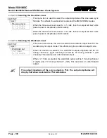
SDI TG 1 


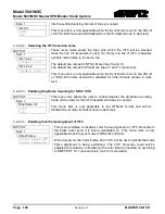
(DST) compensation will be applied to the SDI burn in. 
 
When set to 

Off

, Daylight Saving Time compensation will not be applied to 

the SDI burn in time. 
 
When set to 

On

 the rules set by the 

DST rules

 menu in the 

GENERAL root 

menu will be used to adjust the SDI burn in time (see section 4.5.9.5). 

DST Ctl 


Off 
On 


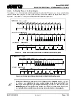
4.4.3.8.  Configuring the SDI Test Generator Output Drive 

OUTPUT 


This menu item is used to control how highdrive on the SDI test 
generator outputs is enabled. Highdrive is a feature that doubles the 
usual SDI output amplitude from the normal  800mV to 1600mV. Most 
equipment cannot accept a highdrive signal properly. Highdrive mode 
should only be used if the output is going to a 5601ACO2 or similar 
resistive attenuator. 
 
Select 

Auto detect ACO

  to have the 5601MSC automatically turn 

highdrive on  when the SNSA and SNSB pins of the AUDIO connector 
are pulled low through connection to a 5601ACO2 (see section 3.1.8). 
Select 

No 5601ACO2

  to disable highdrive for the SDI test generator. 

This is the recommended setting for installations not using a 5601ACO2. 
Select 

5601ACO2 in use

 to turn highdrive on for the SDI test generator. 

The SDI outputs for this test generator will be double amplitude. 

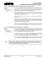
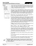
SDI TG 1 


Output Drive 


Auto detect ACO 
No 5601ACO2 
5601ACO2 in use


When the SDI test generator is in highdrive mode, most equipment will not be 
able to receive the SDI signal properly. Leave highdrive disabled unless the SDI 
test generator outputs are connected to a 5601ACO2 automatic changeover. 


4.4.3.9.  Setting the SDI Test Generator Syncro Mode 

OUTPUT 


This menu item controls the behaviour of the SDI TG when the unit is in 
syncro mode. If syncro is not enabled this menu item is ignored. 
 
Select 

Include syncro

  to include the SDI TG in the synchronization of 

menu items between the master and slave units. 
 
Select 

Exclude syncro

  to exclude the SDI TG from synchronizing its 

settings with the master or slave unit. This allows the TG to be modified 
freely on the slave unit to different settings than the master. 

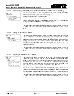
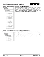
SDI TG 1 


Syncro 


Include syncro 
Exclude syncro 


4.4.4.  Configuring the Analog Video Test Generator Outputs (SDTG, HDTG, 3GTG Options) 

There are two individual Analog Test Generators (ATG 1 and ATG 2). They have identical features. For 
the sake of simplicity, only the menu for ATG 1 will be described in this manual. 

4.4.4.1.  Selecting the Test Pattern for the Analog Video Test Generator Output 

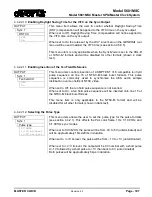
OUTPUT 


This menu item selects the picture content for the analog video test 

Summary of Contents for 5601MSC

Page 1: ...he material contained in this manual consists of information that is the property of Evertz Microsystems and is intended solely for the use of purchasers of the 5601MSC Master Clock SPG Evertz Microsystems expressly prohibits the use of this manual for any purpose other than the operation of the 5601MSC All rights reserved No part of this publication may be reproduced without the express written p...

Page 2: ...This page left intentionally blank ...

Page 3: ...s two blades and a third grounding prong The wide blade or the third prong is provided for your safety If the provided plug does not fit into your outlet consult an electrician for replacement of the obsolete outlet Protect the power cord from being walked on or pinched particularly at plugs convenience receptacles and the point where they exit from the apparatus Only use attachments accessories s...

Page 4: ...l interference to radio communications Operation of this equipment in a residential area is likely to cause harmful interference in which case the user will be required to correct the interference at his own expense This equipment has been tested and found to comply with the limits for a Class A digital device pursuant to the European Union EMC directive These limits are designed to provide reason...

Page 5: ...dential area is likely to cause harmful interference in which case the user will be required to correct the interference at his own expense WARNING Changes or modifications not expressly approved by Evertz Microsystems Ltd could void the user s authority to operate the equipment Use of unshielded plugs or cables may cause radiation interference Properly shielded interface cables with the shield co...

Page 6: ...er REN both of which are on the label on the rear panel The REN is used to determine the number of devices you may legally connect to your telephone line In most areas the sum of the REN of all devices connected to one line must not exceed five 5 0 You should contact your telephone company to determine the maximum REN for your calling area The 5601MSC may not be used on coin service provided by th...

Page 7: ...formation contained in this manual is believed to be accurate and reliable However Evertz assumes no responsibility for the use thereof nor for the rights of third parties which may be affected in any way by the use thereof Any representations in this document concerning performance of Evertz products are for informational use only and are not warranties of future performance either expressed or i...

Page 8: ...Model 5601MSC Model 5601MSC Master SPG Master Clock System Page ii Revision 2 2 REVISION This page left intentionally blank ...

Page 9: ...2 1 1 Sync Outputs 12 2 1 2 Timecode Outputs LTC IRIG 14 2 1 3 Test Generator Options SDTG HDTG 3GTG 15 2 1 4 Global Pedestal Control 15 2 1 5 Global Phase Controls 15 2 2 Genlock 19 2 2 1 Frequency Locking 19 2 2 2 Selecting the Frequency Reference Type 20 2 2 3 Selecting the Genlock Range 20 2 2 4 Lock Type Selection 21 2 2 5 Video Genlock Operation 23 2 2 6 Serial Digital Video Timing 24 2 2 7 ...

Page 10: ... 2 Sync Outputs 57 3 1 3 Ethernet Connections 58 3 1 4 Linear Time Code and IRIG Connections 59 3 1 5 Serial Port Connection 60 3 1 6 GPS Connection 60 3 1 7 GPIO Connections LTC Input Secondary LTC Outputs and Syncro Connections 61 3 1 8 Unbalanced Audio Connections 61 3 1 9 Balanced Audio and Modem Connections 62 3 1 10 Test Generator Connections SDTG HDTG 3GTG options 63 3 1 10 1 Serial Digital...

Page 11: ...1 5 Synchronizing All the LTC and VITC Outputs to System Time Immediately 100 4 4 1 6 Setting the LTC Frame Offset 100 4 4 1 7 Selecting the LTC Time Zone Offset 101 4 4 1 8 Enabling Daylight Saving Time for the LTC Output 101 4 4 1 9 Setting the LTC IRIG Output Level 101 4 4 1 10 Enabling LTC Polarity Correction 102 4 4 1 11 Enabling the LTC Output Color Frame Bit 102 4 4 1 12 Selecting the IRIG ...

Page 12: ...DARS and Wordclock Locking Mode 129 4 4 7 2 Setting the Phase of the AES and DARS Outputs 130 4 4 7 3 Setting the Phase of the Wordclock Outputs 130 4 4 7 4 Selecting the Tones to Generate on the AES Digital Audio Outputs 131 4 4 7 5 Setting the Audio Levels for the AES Digital Audio Outputs 131 4 4 8 Enabling the Setup Pedestal for all Sync and Analog Test Generator Outputs 131 4 4 9 Configuring ...

Page 13: ...9 4 5 12 7 Configuring IP Broadcast Packet Handling 149 4 5 13 Configuring the Network Time Protocol Functions Units fitted with the T option 150 4 5 13 1 Enabling NTP Spoofing 150 4 5 13 2 Configuring the NTP Restrictions 151 4 5 14 Configuring the Precision Time Protocol Master 152 4 5 14 1 Master En 152 4 5 14 2 Master Mode 152 4 5 14 3 Setting the PTP DSCP value 153 4 5 14 4 Setting the Sync R...

Page 14: ...Outputs 170 5 1 13 Power Supplies 171 5 1 14 Compliance 171 5 1 15 Mechanical and Environmental 171 5 1 16 Ordering Options 171 5 2 UPGRADING THE FIRMWARE 172 5 2 1 Overview and Setup 172 5 2 2 Putting the 5601MSC into Upgrade Mode 172 5 2 3 Uploading the Firmware 173 5 2 4 Uploading the Firmware using FTP over Ethernet 173 5 3 SERVICING INSTRUCTIONS AND TROUBLESHOOTING 174 5 3 1 Changing the Fuse...

Page 15: ...d 45 Figure 2 17 Dropframe Timecode with Respect to Real time over a 24 Hour Period 45 Figure 2 18 Daily Time Jam Event for 29 97Hz Dropframe Timecode 46 Figure 2 19 Dropframe Timecode with Respect to Real time over One Week 47 Figure 2 20 Detail of IRIG Alignment to IRIG Datum Pulse 48 Figure 2 21 IRIG Input and Output Connections 49 Figure 2 22 Testing the NTP Server 50 Figure 2 23 Redundant Mas...

Page 16: ... Standard 8 pin Modular Connector Wiring Color Codes 58 Table 3 2 LTC OUT 1 and LTC OUT 2 XLR Pin Definitions 59 Table 3 3 COM Port Pin Definitions 60 Table 3 4 GPS Serial Port Pin Definitions 60 Table 3 5 GPIO Pin Definitions 61 Table 3 6 AUDIO Removable Terminal Block Pin Definitions 62 Table 3 7 Evertz provided GPS Cable part WA T09 Internal Wiring 67 Table 3 8 Accutime Gold Extender Cable 68 T...

Page 17: ...s or pulses or subcarriers Each color black output can optionally carry Vertical Interval Time Code VITC on a user specified set of lines Additionally there are many more sync modes available for each output The wordclock output provides a 48kHz wordclock or may be configured as an additional sync output The 10MHz output provides 10MHz or 5MHz or may be configured as an additional sync output When...

Page 18: ...d time reference GP option Compatible with Evertz Dual GPS Data Fiber Receivers Transmitters 7707GPS series Output frequency stability guaranteed better than 5 0 x 10 9 or 0 005ppm Special Slow lock mode prevents sudden changes in system frequency phase when a reference is lost and regained by slowly retiming the outputs until lock is established Special Wide lock mode allows rapid lock to video o...

Page 19: ... different AC sources for true redundancy If both supplies are not powered the unpowered supply will trigger a system fault A redundant power supply may be added at any time to a unit by removing the fan module and installing the second power supply The Number PS menu item must be changed to the correct setting in order for the power supply fault detection to work properly see section 4 5 9 5 The ...

Page 20: ...signed if SNMP traps are required to be sent to remote logging software such as VistaLINK Pro Contact Evertz customer service if a MIB to the 5601MSC is required 1 1 4 Selecting and Connecting Frequency References Pressing the INPUT button on the front panel will select the input menu From here the frequency and time references of the unit can be configured Use the control knob to select the Frequ...

Page 21: ...cy stability of the 5601MSC will ensure that the acquired time is accurate for a maximum period of 10 days however the unit can be configured to dial out every day or once per week if desired See section 4 5 6 Syncro If the 5601MSC is paired with another unit and connected through a 5601ACO2 automatic changeover it can acquire time and date updates from the master unit Therefore in dual redundant ...

Page 22: ...lt by the end user If a test generator option is installed such as the SDTG HDTG or 3GTG options there will be two channels of balanced analog audio and balanced versions of the AES1 AES2 and DARS outputs available on a 16 pin removable terminal block connector The removable terminal block can be unscrewed from the 5601MSC to be wired up then inserted and secured with the two slotted flange screws...

Page 23: ...est Generator Outputs If the unit has been equipped with a test generator option such as the SDTG HDTG or 3GTG options then there will be several test generator outputs available The video test generator outputs include two composite analog video test generators that are configured in menus ATG 1 and ATG 2 There are four serial digital video test generators each with two BNC outputs These are conf...

Page 24: ...1 evt ts1920smscHDq1 evt FTP can also be used to upgrade the application To send the application the ftp must be enabled To do this enter GENERAL then enter Firmware then enter Enable FTP This will enable sending files to the 5601MSC for 15 minutes To send the application enter send filename a 5601MSC bin Where filename is the name of the file in the computer for example send 5601MSC_2v5b4 bin A 5...

Page 25: ...ts If the 5601MSC has any of the test generator options installed timecode can be burned in at the bottom of the test signal output The time is controlled by the TC Burn In Dropframe Ctl Set Jam Time Jam Output Jam all VitcLtc Time Offset Time Zone and DST enable menu items 1 1 11 Final Steps of Set Up and Securing all Connections Once the 5601MSC has been configured the various STATUS screens sho...

Page 26: ...Model 5601MSC Model 5601MSC Master SPG Master Clock System Page 10 Revision 2 2 OVERVIEW This page left intentionally blank ...

Page 27: ...mecode burn in Text Message 16 ch Audio Embedder Text Message Timecode burn in 16 ch Audio Embedder CF H V Fine Phase Control CF H V Fine Phase Control H V Phase Control H V Phase Control SERIAL DIGITAL VIDEO TEST GENERATOR 2 Timecode burn in Timecode burn in Text Message Timecode burn in 16 ch Audio Embedder H V Phase Control Text Message Timecode burn in 16 ch Audio Embedder H V Phase Control DI...

Page 28: ...TSC M PAL B There are two color black output modes one in NTSC M format and the other in PAL B format These modes are referred to as black burst or color black because they contain black video and have a colorburst to provide a colorframe reference Vertical Interval Time Code VITC can be inserted on up to two lines in these modes Additionally a SMPTE ST 318 ten field reference can be inserted onto...

Page 29: ... field information The 1080i 60 1080i 59 94 and 1080i 50 formats should be used instead whenever possible Continuous Wave CW Signals 10MHz 5MHz NTSC Subcarrier PAL Subcarrier The continuous wave CW output modes produce a sine wave at a specific frequency The 10MHz and 5MHz outputs are locked in frequency to the reference but are not phased with respect to the reference The NTSC Subcarrier 3 579MHz...

Page 30: ...be high during PAL color field 1 It will only be phase locked when referenced to GPS or a PAL B reference see Figure 2 4 The IRIG1 Datum pulse will go high at the start of the IRIG second for 100ms This pulse will be aligned within 20 microseconds of the GPS 1PPS pulse when locked to a GPS reference 2 1 2 Timecode Outputs LTC IRIG GPIO LTC IRIG OUTPUT 1 LTC IRIG OUTPUT 2 There are two LTC IRIG out...

Page 31: ...each with two outputs on BNC connectors The SDTG option provides the capability to generate Standard Definition formats The HDTG option adds the ability to generate High Definition formats The 3GTG option adds the ability to generate 3G formats as well as dual link formats The 3GTG option also includes 3D test patterns in various formats All test generators have an audio embedder and can generate ...

Page 32: ...tputs affected and the minimum phasing resolution for each The outputs unaffected by global phase will remain locked to the reference The Global Phasing menu in the OUTPUT root menu is used to configure global phase Output Affected by Global Phase Minimum Phasing Resolution Sync NTSC PAL modes Yes 1 ns Sync Tri level modes Yes 1 ns Sync Slo PAL modes Yes 1 ns Sync 5MHZ 10MHZ CW modes No Sync NTSC ...

Page 33: ... Amplitude Modulated 1kHz Sinewave P 0 IRIG B127 100 bits second LEGEND Pr Reference Bit P 0 P 9 Position Identifier Bits M Index Marker Bit always 0 29 97Hz LTC VITC field 1 line 14 Field 1 NTSC Black Burst One Frame 33 367ms Field 2 VITC field 2 line 14 Sync Word 1 Frames 1 1 0 0 BG1 0 0 0 0 0 10Fr 1 1 1 0 1 0 1 0 1 0 BG2 Seconds BG3 0 1 0 0 1 0 1 10sec 1 BG4 0 1 1 0 Minutes 0 0 0 1 BG5 0 0 0 0 ...

Page 34: ...F2 F3 F4 7 8 9 10 F1 F2 F3 F4 1 2 3 4 F1 F2 F3 F4 5 6 7 8 F1 F2 F3 F4 9 10 1 2 F1 F2 F3 F4 3 4 5 6 F1 F2 F3 F4 7 8 9 10 F1 F2 F3 F4 1 2 3 4 F1 F2 F3 F4 5 6 7 8 F1 F2 F3 F4 9 10 1 2 F1 F2 F3 F4 3 4 5 6 F1 F2 F3 F4 7 8 9 10 F1 F2 F3 F4 7 8 9 10 F1 F2 F3 F4 5 6 F3 F4 1 2 3 4 F1 F2 F3 F4 5 6 F1 F2 PAL B 00 23 VITC ss ff 00 24 01 00 01 01 PAL color frame pulse 1Hz Pulse 1pps 1080i 60 F1 F2 F1 F2 F1 F2 ...

Page 35: ...ncy and phase of the reference signal In narrow mode an additional feature is available whereby the adjustment rate of the oscillator is limited to prevent sudden changes during a re locking operation see Slow mode in section 2 2 4 The 5601MSC can lock to several different frequency reference types The supported signal types are shown in Table 2 2 Video and Continuous Wave CW signals are applied t...

Page 36: ...or OCXO is used and the VCXO runs as backup When Wide is selected the voltage controlled quartz oscillator VCXO is used and the OCXO runs as backup It should be noted that when the frequency reference source is set to GPS or Internal Ref the genlock range is forced to Narrow mode OCXO regardless of this menu setting In the event that the frequency reference is lost the 5601MSC will free run using ...

Page 37: ...e ability to lock to a precision frequency source such as GPS or a rubidium cesium frequency standard Such frequency sources are extremely accurate The oscillator is guaranteed from the factory to lock to such a reference within 10 of the center of its tuning range The aging of the oscillator is 10 maximum for the first year and 5 for every year thereafter This translates to an expected lifetime o...

Page 38: ... immediately lock to the reference by performing a frequency jam This can be performed by selecting Jam Reference in the Jam Input menu off the INPUT root menu It can also be performed remotely through SNMP Once the Jam Reference has been initiated the frequency and phase from the reference is jammed into the main oscillator forcing it to lock immediately Performing a Jam may cause disturbances on...

Page 39: ...Frames NTSC M 10field Sync edge Burst 5 Frames PAL B Sync edge Burst 4 Color Frames 625i 48 Sync edge 1 Frame 625i 47 95 Sync edge 1 Frame 1080i 60 Sync edge 1 Frame 1080i 59 94 Sync edge 1 Frame 1080i 50 Sync edge 1 Frame 1080p 60 Sync edge 1 Frame 1080p 59 94 Sync edge 1 Frame 1080p 50 Sync edge 1 Frame 720p 60 Sync edge 1 Frame 720p 59 94 Sync edge 1 Frame 720p 50 Sync edge 1 Frame 720p 24 Sync...

Page 40: ...show correct alignment of a serial digital video source to a supplied external analog reference These devices appear to have been calibrated to the output of an unknown video DAC This means they will not display correct SMPTE timing due to the delay introduced in the measurements by the DAC process Since the outputs of the 5601MSC are aligned using SMPTE timing their phase must be advanced signifi...

Page 41: ...come frequency locked This frequency locking process uses both the horizontal sync and the colorburst to obtain an accurate lock The applied NTSC reference should have no video content and a low Subcarrier to Horizontal SCH offset to assure proper lock The approximate SCH value is shown in the Inputs status screen see section 4 1 2 If the SCH error is higher than 30º the 5601MSC will fall back to ...

Page 42: ...ked to the same reference The phase may also change if the unit is restarted The phase locking ability of the 5601MSC when supplied with an NTSC reference is summarized at the bottom of the lock diagram Figure 2 7 The HD standards listed apply to both the HD test generators and the tri level sync outputs The serial digital video test generator outputs are phased according to SMPTE compliant timing...

Page 43: ...TE ST 318 the phase locking ability of the 5601MSC is enhanced The ten field reference provides 5 frames worth of phasing information that allows deterministic locking of 23 98Hz standards the 6 1 001Hz pulse and DARS AES signals These outputs can be guaranteed to be the same phase between multiple units The color frame sequence of the NTSC reference is also decoded and used for phasing NTSC sync ...

Page 44: ... match The AES DARS outputs provide a fixed sample rate of 48kHz 48 000 samples per second This means that during a single NTSC frame 1601 6 AES frames will have been generated It takes five NTSC frames to fit a whole number of AES frames 8008 frames This means that 48kHz AES DARS will line up evenly with NTSC sync once out of every five frames and during the other four frames the AES DARS wavefor...

Page 45: ...uence is decoded from the PAL reference and provides a 4 frame phase reference As with NTSC references the 5601MSC locks to both the horizontal sync edges and colorbursts of the PAL reference If the Subcarrier to Horizontal sync error is higher than 30º the 5601MSC will fall back to horizontal sync edge locking only If the SCH error is higher than 50º or the colorburst cannot be measured the unit ...

Page 46: ...to line 1 of the PAL reference as illustrated in lock diagram 3 of Figure 2 10 A PAL reference provides enough information for phasing of 50Hz and 25Hz standards but does not provide a long enough phase period to deterministically phase 60Hz or 24Hz standards The standards that can be phased properly are listed at the bottom of lock diagram 3 Figure 2 10 The HD standards listed apply to both the H...

Page 47: ...signals The main oscillator frequency is locked to the rising edge of the tri level waveform The phase information provided by tri level reference signals is limited and each signal standard can only be used to deterministically phase lock standards of a similar frame rate Lock diagram 4 above gives an example for 1080i 59 94 tri level sync Refer to Table 2 5 for a summary on the phase locking cap...

Page 48: ...RS 23 98Hz LTC 1080p 23 98sF 625i 47 95 1080p 23 98 1080p 23 98sF AES DARS 23 98Hz LTC 1080p 24 625i 48 720p 24 1080p 24 1080p 24sF AES DARS 24Hz LTC 1080p 24sF 625i 48 720p 24 1080p 24 1080p 24sF AES DARS 24Hz LTC 1080p 25 PAL 625i 50 1080i 50 720p 50 1080p 25 576p 50 AES DARS 25Hz LTC Table 2 5 Phase Locking to HD Tri Level Standards 2 2 11 Slo PAL Genlock The 5601MSC supports two Slo PAL refere...

Page 49: ...odel 5601MSC Model 5601MSC Master SPG Master Clock System OPERATION Revision 2 2 Page 33 2 2 12 Continuous Wave and Internal References Figure 2 12 Lock Diagram 5 10MHz and Internal Frequency References ...

Page 50: ...se relationship as long as the CW reference is uninterrupted and the unit is not restarted If a restart does occur the 10MHz Global Phase controls are automatically disabled and reset to zero at startup When a CW reference is used the phase of the DARS and AES outputs can be anchored to either NTSC or PAL standards This is chosen using the AES DARS WC lck menu item in the AES Audio menu This menu ...

Page 51: ... GPS receiver GP option the unit can lock in frequency and phase to the high accuracy timing provided by the GPS satellites The main oscillator frequency is locked to the 1 pulse per second PPS timing pulse provided by the receiver Because of the low rate of this timing pulse only the high stability OCXO oscillator can be used and the Genlock Range control will be forced to Narrow regardless of th...

Page 52: ...ncy accuracy there can be issues dealing with limited availability and phase errors A GPS reference can be described as a soft lock As more satellite signals are discovered the phase accuracy of the GPS lock improves However there will always be some wander associated with GPS lock due to uncontrolled variables such as atmospheric disturbances and terrestrial interference This can cause problems w...

Page 53: ...t generator output have their own independent clock The timecode clocks are synchronized to the system clock once a day at user specified times This allows for timecode rates that do not count in real time Note that NTP and IRIG time is derived directly from the system clock Figure 2 14 Time Locking Block Diagram The system clock time date is constantly compared to the time date that is provided b...

Page 54: ...enerated It is still possible to synchronize the system clock to the time reference by performing a manual time jam This mode is useful when a time reference is not being used or is not always available User When the time comparator detects a difference between the system clock and the time reference it will notify the operator with a jam warning The message TIME JAM NEEDED will be displayed on th...

Page 55: ...ich means the need for a leap second cannot be predicted more than six months in advance If a leap second is necessary it will occur at the end of the day usually on either June 30th or December 31st Refer to www iers org for more information and bulletins on upcoming leap seconds Leap seconds can cause complications with 25Hz LTC or PAL VITC See the timecode note in section 2 3 4 2 3 for more inf...

Page 56: ...ce The two protocols supported at this time are NIST Automated Computer Time Service and NRC Computer Time Date The modem is configured using the Modem menu in the GENERAL root menu as described in section 4 5 6 After a time service has been selected the phone number is entered and the 5601MSC can be configured to automatically dial at a specific time once a day or once a week The dial time should...

Page 57: ... information the date decoder must be disabled put into No date mode to prevent false date decoding and spurious jam events When date decoding is disabled the date can be set manually using the Set System Date menu item located in the GENERAL root menu The 5601MSC will continuously compare the system clock to the incoming LTC time and date When a difference of more than 2 milliseconds is detected ...

Page 58: ...e before being jammed into the output s timecode clock In order to use VITC as a time reference the frequency reference must be set to Video 2 3 3 6 IRIG Time Reference When the IRIG option is installed the 5601MSC will be able to read IRIG B timecode that is applied to the LTC input on the GPIO connector The IRIG type is auto detected Refer to section 2 3 5 for more information on the IRIG B form...

Page 59: ...utput waveforms are aligned to video so that the end of the sync word lines up with the start of the field1 vertical sync This occurs on line 4 for the NTSC standard and line 1 for the PAL standard Vertical Interval Time Code can be inserted onto any black burst sync output and is inserted onto a vertical blanking line once per field twice per frame See Figure 2 15 for LTC and VITC timing relation...

Page 60: ... Counting Because the 29 97Hz rate is used extensively as timecode for video reference signals a method was developed to allow reasonably precise time keeping with the non real time rate This method involves dropframe counting Since the 29 97Hz rate runs slower than real time dropframe counting skips over certain frame counts in order to periodically catch up to real time Frame counts are always s...

Page 61: ...601MSC Master SPG Master Clock System OPERATION Revision 2 2 Page 45 Figure 2 16 Dropframe Timecode with Respect to Real time Over 1 Hour Period Figure 2 17 Dropframe Timecode with Respect to Real time over a 24 Hour Period ...

Page 62: ... to real time Dropframe timecode counts an entire 24 hour period 86 4 milliseconds faster than real time This is the equivalent of 2 59 frames of video At the daily jam event when the timecode clock is jammed to the system clock some extra frame counts will have to be inserted to bring the timecode closer to real time It is not possible to adjust by fractional frame counts Either 2 or 3 frame coun...

Page 63: ... time It can be expected that eventually a 2 frame offset may appear between dropframe timecode across multiple 5601MSC units Figure 2 19 Dropframe Timecode with Respect to Real time over One Week 2 3 4 2 3 Color Frame Alignment to PAL Color frame alignment to PAL video can be enabled for 25Hz LTC timecode and for any PAL sync VITC output or PAL analog TG output burn in window The 25Hz timecode ru...

Page 64: ...y time a leap second occurs 2 3 5 IRIG Timecode When equipped with the IRIG option the 5601MSC is capable of generating IRIG B timecode from the LTC outputs and can also read IRIG B timecode on the LTC input The IRIG B formats supported are shown in Table 2 8 All IRIG B formats are based on 100 bit timecode that is amplitude modulated with a 1kHz sine wave carrier The differences between the four ...

Page 65: ...s in their respective menus See section 4 4 1 for a description of the menu settings The IRIG signal amplitude can be controlled by the Output Level menu item When an LTC output has been configured to an IRIG output mode both primary and secondary outputs will provide the same IRIG signal The 5601MSC can also be configured to the IRIG B as a time reference The time reference source must first be s...

Page 66: ...quest for NTP time is received by the 5601MSC the source IP address is checked against a list of NTP restrictions see section 4 5 13 2 There are a total of eight restrictions and they are checked sequentially If the incoming request passes all eight restrictions the NTP server will respond It is possible to perform a quick validation of NTP operation using a Windows XP or Windows 2000 PC that is c...

Page 67: ... three satellite ranges would be sufficient to calculate a position In real world applications the clock in the receiver will not be an atomic clock and the smallest error in frequency will cause huge errors in positioning Consequently a fourth satellite range is incorporated to solve for timing error in the receiver This allows the receiver to correct its clock and synchronize it to within nanose...

Page 68: ...satellites do not meet the elevation SNR or PDOP criteria and cannot be used Attempting to detect more satellites GPS Ok Sig OK The receiver has completed a self survey and as operating normally GPS 1 Good Sat The receiver has previously completed a self survey and is maintaining synchronization while tracking just one satellite GPS 8 Good Sats The receiver is operating in over determined clock mo...

Page 69: ...e i e 1 year or more of the GPS receiver being disconnected or obscured from the sky If the GPS receiver is removed for 5 minutes and then returned the unit will take nominally less then 5 minutes to fully re lock If the GPS receiver is removed for 15 minutes and then returned the unit will take nominally less than 20 minutes to fully phase lock to the GPS system time 2 5 4 GPS Position Insertion ...

Page 70: ...ical infrastructure requirements a 5601ACO2 can be used to connect two 5601MSC units in a dual redundant configuration The 5601ACO2 monitors signal health to decide which of the 5601MSC units will be connected to the downstream outputs See the connection diagram below Figure 2 23 Redundant Master Clock SPG with Auto Changeover System Diagram ...

Page 71: ...l be copied to the slave unit automatically This assures minimum impact should a changeover event occur The 5601ACO2 simplifies wiring by providing a single point of entry for an LTC reference and GPIs for both 5601MSC units The LTC input to the 5601ACO2 is internally split to both master and slave units Similarly the GPI inputs are split to both units allowing any GPI trigger to affect both units...

Page 72: ...Model 5601MSC Model 5601MSC Master SPG Master Clock System Page 56 Revision 2 2 OPERATION This page left intentionally blank ...

Page 73: ...ovide six independent programmable sync outputs that are configured by the SYNC 1 to SYNC 6 group of sub menus in the OUTPUT setup menu Each output can be configured for any format of sync output from black burst to tri level to 5MHz 10MHz to wordclock and more See section 4 4 2 10 MHz OUT This BNC connector provides a 10MHz frequency reference but can also be programmed as another sync output It ...

Page 74: ...A color code wiring chart is provided in Table 3 1 for the current Ethernet standards AT T 258A or EIA TIA 258B color coding shown Also refer to the notes following the table for additional wiring guide information Pin Signal EIA TIA 568A AT T 258A or EIA TIA 568B 10BaseT or 100BaseTX 1 Transmit White Green White Orange X 2 Transmit Green Orange X 3 Receive White Orange White Green X 4 N A Blue Bl...

Page 75: ... load impedance of greater than 1kΩ There are two 3 pin male XLR connectors for SMPTE EBU Linear Time Code When the IRIG option is installed these outputs will also be able to provide IRIG timecode They are labelled LTC OUT 1 and LTC OUT 2 These XLR connectors are the primary copies for each timecode output The LTC OUT 1 connector is capable of driving 12 VDC power for downstream Evertz clocks see...

Page 76: ...2 TxD RS 232 Transmit Output 3 RxD RS 232 Receive Input 4 5 Signal Gnd RS 232 Signal Ground 6 7 RTS RS 232 RTS Input 8 CTS RS 232 CTS Output 9 Table 3 3 COM Port Pin Definitions 3 1 6 GPS Connection A 9 pin female D connector for connecting the optional GPS receiver GP option Table 3 4 shows the pinout of the port See section 3 5 for information about mounting and connecting the GPS receiver Pin N...

Page 77: ...und 7 GND Signal Ground 8 Syncro Tx Syncro Transmit 9 Syncro Rx Syncro Receive 10 GND Signal Ground 11 LTC Input Linear Time Code Input 12 LTC1 Out Secondary Linear Time Code Output 1 13 LTC2 Out Secondary Linear Time Code Output 2 14 GPI 1 General Purpose Input 1 15 GPI 2 General Purpose Input 2 Table 3 5 GPIO Pin Definitions 3 1 8 Unbalanced Audio Connections AES 1 2 These two BNC connectors pro...

Page 78: ...NSA SNSB GND GND AES 1 AES 1 AES 2 AES 2 DARS DARS Table 3 6 AUDIO Removable Terminal Block Pin Definitions The ANALOG AUDIO sub menu in the OUTPUT root menu is used to configure the analog audio outputs The SNSA and SNSB pins are used by the 5601MSC to detect connection to a 5601ACO2 and automatically enable highdrive They may be left unconnected if this functionality is not desired MODEM The MOD...

Page 79: ...re two independent composite analog video test generators each with a single BNC output The output formats are compatible with SMPTE ST 170 or ITU R BT 1700 1 The ATG1 and ATG2 sub menus in the OUTPUT root menu are used to configure these outputs BNCs Analog Test Generator 1 BNC is labeled ATG1 Analog Test Generator 2 BNC is labeled ATG2 3 1 11 Power Connections The 5601MSC has one or two redundan...

Page 80: ...at A system fault is activated when the temperature inside the unit exceeds operating limits 3 3 CONNECTING THE GENERAL PURPOSE INPUTS AND OUTPUTS The 15 pin female GPIO connector has 2 general purpose inputs and 2 general purpose outputs The GPI inputs are active low This means that if an input is floating not connected then it will not be activated The GPIs can be activated by connecting the GPI...

Page 81: ...ls When syncro menu mode is active all of the menu settings in the OUTPUT root menu are copied from the master 5601MSC to the slave unit The menu settings in the INPUT and GENERAL menus are not affected by syncro In the OUTPUT menu the SDI TGs and ATGs can be excluded from syncro This can be done individually for each test generator see sections 4 4 3 9 and 0 3 5 GPS RECEIVER INSTALLATION GP OPTIO...

Page 82: ...t The smart antenna is designed for a pole mount with a 1 14 straight thread which is a common marine antenna mount For stationary installations a 3 4 pipe thread can be used but a 1 14 straight thread is recommended Pole mounting is illustrated in Figure 3 4 Secure the mounting pole to a solid structure so that it is oriented vertically Thread the smart antenna onto the pole or pile and hand tigh...

Page 83: ...interface cable to the location of the 5601MSC unit using the most direct path Avoid routing the cable near hot surfaces sharp or abrasive surfaces or corrosive fluids or gases Avoid sharp kinks or bends in the cable Additional protection such as heat shrink tubing may be required to protect the cable jacket at points where the cable enters the building especially if the opening is rough or sharp ...

Page 84: ...able 3 8 3 5 3 System Start up At power up the smart antenna will automatically begin to acquire and track the GPS satellite signals From a cold start the smart antenna will normally take from 2 to 5 minutes to lock on to sufficient satellites to accurately determine the time Refer to section 2 5 2 for more information During this time the Lock Status and Inputs status screens on the front panel w...

Page 85: ...CD displays are used to display the menu system and the current position within the menu tree There are also messages on the left LCD that indicate system status Sections 4 3 to 4 5 give detailed information on the specific operations required to control the 5601MSC 4 1 1 Front Panel Buttons There are four buttons to the right of the control knob that are used to select the four main root menus Th...

Page 86: ...es When in the menu or a selection list pressing the control knob has the same effect as pressing the SELECT button When adjusting a numerical value depressing the control knob while turning it will increment or decrement in larger steps of 16 4 1 2 The Status Screens There are several status screens available on the 5601MSC that can be accessed by pressing the STATUS button on the front panel Eac...

Page 87: ...System In time status screen shows the system clock time and date on the first two lines The third line prefixed with L i shows the current LTC timecode being read from the LTC IRIG input if present If the LTC input is lost the time shown here will be replaced with If drop frame is detected the last colon will be replaced with a period The fourth line prefixed with V i shows the current timecode b...

Page 88: ... they have been configured to output IRIG the current output timecode will be shown on lines 4 or 5 prefixed with I1 or I2 If the Wordclock or 10MHz outputs have been configured to output black burst with VITC enabled these clocks will be displayed on lines 3 and 4 as bright white In the example to the left the Wordclock and 10MHz output have been left in their default modes cannot insert VITC ont...

Page 89: ...ected as a frequency or time reference The fifth line displays the current GPS lock state and the sixth line displays how many healthy satellite signals the GPS antenna is receiving See section 2 5 2 for an explanation on the GPS lock process Fan PS status Dual power supplies Single power supply The Fan PS status screen displays the status of the power supplies and exhaust fans at a glance The fir...

Page 90: ...w LTC ok IRIG n a If IRIG is present it will show LTC n a IRIG ok The sixth line shows the status of the General Purpose Inputs These GPI inputs are activated by connection to ground The status will be GPI1 LO or GPI2 LO when either GPI has been activated See section 3 3 for information on the GPIs Modem ACO2 Hw No modem option SNMP read only Modem inactive SNMP fully enabled link to 5601ACO2 bank...

Page 91: ...nd fifth lines display the Ethernet MAC address for the port The last line shows the Ethernet link status It will show Ethernet link ok if an Ethernet connection is established and No Ethernet link otherwise NTP The NTP status screen displays information about the NTP server It shows stratum precision lock status and reference It will also show if there are issues with the NTP The HELP button will...

Page 92: ...CD Displays in Status Screen The left LCD display shows the current position in the menu tree In the bottom left corner the system status is shown A critical fault will appear in red blinking text The possible system status messages are summarized in Table 4 1 in order of severity Message Description Hw fail Appears blinking red in the bottom left corner Indicates that an internal hardware problem...

Page 93: ...isplayed on the right LCD The character is used as a selection cursor to show which menu item is currently selected Use the and buttons or turn the control knob to move the character beside the desired sub menu and press the SELECT button to enter it The menu tree is shown on the left LCD and identifies which menus have been entered Press the ESC button to return to the previous level in the menu ...

Page 94: ...g phase of the sync outputs or when adjusting the analog audio levels Proceed with caution and press the ESC button to return to the previous menu without making a change See Figure 4 6 below as an example Figure 4 6 Adjustment Live Control Sections 4 3 to 4 5 provide detailed descriptions of the INPUT OUTPUT and GENERAL menus The tables in these sections are arranged in an indented structure to d...

Page 95: ...me Reference Src GPS Modem Syncro LTC VITC None IRIG SNTP Vitc Line line 14 VitcLtc Date Auto Mode No date Legacy Production SMPTE 309 BCD SMPTE 309 MJD Irig Mode B12 AUTO B120 to B123 B124 to B127 Time IP NTP IP 1 NTP IP 2 NTP IP 3 NTP IP 4 NTP IP 5 NTP IP 6 NTP IP 7 NTP IP 8 NTP IP Mode IP disabled IP enabled NTP IP Address 10 0 0 1 Lock Type User Never Always Daily Input Jam Time Input Jam Time...

Page 96: ...MMED Time offset 0 frames Time zone 0 00 hours DST Ctl Off On Output Level level 7 Parity Parity Off Parity On Color Frame Color Frame Off Color Frame On Irig mode B122 B123 B124 B127 Irig offset LIVE 0 seconds SYNC 1 1 2 3 4 5 6 Or 10 MHz Or Wordclock Mode PAL B NTSC M 1080i 50 1080i 59 94 1080i 60 1080p 23 98 1080p 23 98sF 1080p 24 1080p 24sF 1080p 25 1080p 29 97 1080p 30 1080p 50 1080p 59 94 10...

Page 97: ...0 Hor phase LIVE Vert phase LIVE Color phase LIVE Pulse type 5V CMOS 1V bi level 1V tri level Sine wave level 1 Volts 2 Volts Wordclock levl 5V CMOS 1 Volts SDI TG 1 1 2 3 4 Signal BLACK WHITE FIELD IDENT B 1 W 2 FRAME IDENT 100 COLORBARS 75 COLORBARS 75 BARS W 100 WHITE RP219 COLORBARS LAB BARS MOVING BOX VALID RAMP 100 WHITE WINDOW 50 WHITE WINDOW 20 WHITE WINDOW SDI CHECKFIELD GREY QUIET GREY A...

Page 98: ...x720p 60 1920x1080p 59 1920x1080p 50 1920x1080p 50 Sample Struct 422 10 YCbCr 444 4 10 YCbCr 444 4 10 RGB 444 12 YcbCr 444 12 RGB 422 12 YCbCr Hor Phase LIVE Phase value Vert hor 0 0 Vert Phase LIVE Audio Group 1 2 3 4 Group Ctl Off On Ch 1 frequency 1 0 kHz Ch 1 level 20 dBFS Ch 2 frequency 1 0 kHz Ch 2 level 20 dBFS Ch 3 frequency 1 0 kHz Ch 3 level 20 dBFS Ch 4 frequency 1 0 kHz Ch 4 level 20 d...

Page 99: ...ULSE AND BAR 100 Y SWEEP 60 Y SWEEP 75 COLOR BARS 100 COLOR BARS SMPTE BARS NTC7 COMPOSITE NTC7 COMBINATION FCC COMPOSITE FCC MULTIBURST 60 EXTENDED MB Y MULTIPULSE 2T PULSE BAR SIN X X COMPOSITE SIGNAL Image Format 525 NTSC M 625 PAL B Fine phase LIVE Phase value cf v h fine 1 1 1 0 0 Hor phase LIVE Vert phase LIVE Color phase LIVE Message Ctl Message Off Message 1 line Message 2 lines H position...

Page 100: ... 00 00 every minute every hour Audio type mute constant left constant right constant both beep left beep right beep both bell left bell right bell both beep l const r beep r const l bell l const r bell r const l Left Frequency 20Hz 12 0kHz Right Frequency 20Hz 12 0kHz Duration 0 1 Seconds Test event LIVE BEEP TEST AES Audio AES DARS WC lck PAL integer NTSC fractional AES coarse LIVE AES DARS WC Ph...

Page 101: ...PS uS LIVE GPS nS LIVE Video ph En Global Ph Off Global Ph On Video mS LIVE Global phasing MS US NS 0 0 0 Video uS LIVE Video nS LIVE Ten MHz ph En Global Ph Off Global Ph On Ten MHz mS LIVE Global phasing MS US NS 0 0 0 Ten MHz uS LIVE Ten MHz nS LIVE Internal ph En Global Ph Off Global Ph On Internal mS LIVE Global phasing MS US NS 0 0 0 Internal uS LIVE Internal nS LIVE Table 4 3 Output Menu Sy...

Page 102: ...m Modem Mode No auto dialAns Auto answer Auto dial Auto dialAnswer Modem standard NRC format NIST format Modem volume Speaker off Speaker on Modem number Modem number 16137453900 Auto dial time Auto dial time 0 00 00 Auto dial day Sunday Monday Tuesday Wednesday Thursday Friday Saturday Every day Dial Now Dial Now LIVE DIALING MODEM Cancel Call Cancel Call LIVE CANCELING CALL Modem Retries 0 retri...

Page 103: ... 4 Ctl Trap IP disabld Trap IP enabled Trap4 IP Add 0 0 0 0 Freq Ref Trap Trap disabled Trap enabled Time Ref Trap Freq Ref JamTrp Time Ref JamTrp LF Fan Fail Trp LR Fan Fail Trp RF Fan Fail Trp RR Fan Fail Trp PSL Fail Trap PSR Fail Trap Hw Fail Trap Overtemp Trap GPI 1 Trap GPI 2 Trap Menu Access Ctl MASTER Access All Menus Norma Menu Locks On Set Time Menu Accessible Menu Locked Set Date VITC L...

Page 104: ... Clock SDI TG 1 All items On Menu Locked Phasing only Test Sigs only PhasingTestSig SDI TG 2 SDI TG 3 SDI TG 4 ATG 1 ATG 2 Analog Audio Menu Accessible Menu Locked AES Audio Global Pedestal Global Phasing Number PS One Power Suppl Dual Pwr Supply Reset GPS LIVE TIME JAMMED DST rules DST mode day week month day of month Start Hour DST starts 0000 DST start day Sunday Saturday or Day1 Day31 DST star...

Page 105: ...Pre EUROPE Live Save preset 1 LIVE SAVED PRESET 1 Save preset 2 LIVE SAVED PRESET 2 Save preset 3 LIVE SAVED PRESET 3 IP Control Ctrl IP address 172 21 56 01 Ctrl IP netmask 255 255 255 0 Time IP address 192 168 56 01 Time IP netmask 255 255 255 0 IP gateway 0 0 0 0 IP gateway en gateway off gateway on Broadcast mode ctrl en time e ctrl rej time e ctrl en time r ctrl rej time r NTP rules NTP spoof...

Page 106: ...m the GPS smart antenna Selecting this option forces the Genlock Range to Narrow All outputs are phased with respect to a specific date in GPS time This forces the time reference to GPS time The GPS disciplined internal oscillator will maintain superb long term accuracy Refer to section 2 2 13 for more information When set to 10 MHz the 5601MSC will look for a 10MHz or 5MHz frequency reference on ...

Page 107: ...d then regained or experiences a change See section 2 2 4 for more information In Abrupt mode whenever the 5601MSC detects that its internal oscillator is no longer synchronized to the reference it will make a sudden change to bring it back into lock This may cause disturbances to the outputs as the unit shifts its frequency and phase In Slow mode when the 5601MSC detects that its internal oscilla...

Page 108: ...and must be either 29 97fps dropframe or 25fps See section 2 3 3 4 for more information When set to VITC the 5601MSC system time will be referenced to time read from Vertical Interval Time Code off a black burst reference applied to the REF IN LOOP BNCs The incoming VITC frame rate can be either 29 97fps dropframe on NTSC M or 25fps on PAL B The line to read VITC from is selected by the Vitc Line ...

Page 109: ...ith Leitch master clock systems Select Production to decode the date in a format compatible with timecode smart slates used in film and television production In this mode the date is encoded as yymmddrr where rr is the nominal frame rate of the respective output 30 for 29 97Hz outputs Select SMPTE 309 BCD date to decode the date in the SMPTE ST 309 standard Binary Coded Decimal mode In this mode t...

Page 110: ... provided by the servers Time Time IP NTP IP 1 NTP IP 2 NTP IP 3 NTP IP 4 NTP IP 5 NTP IP 6 NTP IP 7 NTP IP 8 NTP IP Mode IP disabled IP enabled 4 3 9 Selecting the SNTP IP Address INPUT The NTP IP address defines the IP address of one of the eight NTP servers that can be used as an SNTP time reference These are valid only when the time reference has been set to SNTP Up to 8 servers can be set up ...

Page 111: ...ange in the time reference will be immediately applied to the system time of the 5601MSC If Daily is selected the 5601MSC system clock will run independently from the time reference and jam once daily at the time of day specified by the Input Jam Time control Time Lock Type User Never Always Daily If the time reference has been set to SNTP the time lock type is forced to Daily no matter what this ...

Page 112: ...ency reference The word Jam here is used in the context that the timing and phase measured on the reference will be jammed into the system oscillator forcing it into synchronization This can cause glitches on all outputs of the 5601MSC and should be used with caution To perform a jam of the frequency reference select the Jam Reference menu item and press the SELECT button Jamming the Time Referenc...

Page 113: ...res the Sync 5 output SYNC 6 Configures the Sync 6 output 10 MHz Configures the 10MHz output Wordclock Configures the Wordclock output SDI TG 1 Configures the SDI Test Generator 1 output SDI TG 2 Configures the SDI Test Generator 2 output SDI TG 3 Configures the SDI Test Generator 3 output SDI TG 4 Configures the SDI Test Generator 4 output ATG 1 Configures the Analog Video Test Generator 1 output...

Page 114: ...e of simplicity only the menus for LTC output 1 will be described in the manual 4 4 1 1 Selecting Normal or Powered LTC 1 Output LTC1 XLR Output Only OUTPUT This menu item controls whether the primary LTC 1 output available on the 3 pin XLR connector will be a standard SMPTE ST 12 1 signal or whether it will be modulated to drive Evertz 1200 series clocks operating in slave mode The secondary LTC ...

Page 115: ...using the SMPTE Dropframe counting sequence and has a bit rate of approximately 2397 bits per second This LTC will run approximately 2 6 frames per day faster than real time This timecode will be synchronous to video sync pulse outputs in the NTSC M 1080i 59 94 and 720p 59 94 video standards Select 25 FPS to generate timecode that counts at 25 frames per second and has a bit rate of 2000 bits per ...

Page 116: ...system time immediately This synchronization will also happen once per day at the time specified using the Set Jam Time menu item see section 4 4 1 3 Caution This menu item is a live control To synchronize the LTC time immediately enter the Jam Output menu item and then press the SELECT button The left LCD screen will display TIME JAMMED in yellow for 2 seconds to show the time has been synchroniz...

Page 117: ...me Use the and buttons or turn the control knob to move the cursor to select the desired time zone offset Press the SELECT button to choose the indicated value It will then become highlighted to show it is the active value LTC 1 Time zone 12 00 hours to 12 00 hours 4 4 1 8 Enabling Daylight Saving Time for the LTC Output OUTPUT This menu item allows the user to control whether Daylight Saving Time...

Page 118: ...ondropframe to NTSC and 25 FPS rates to PAL When set to Color Frame Off the color frame bit will always be set to 0 When set to Color Frame On the color frame bit will be set to 1 to indicate color frame synchronization and the timecode will be forced to align to its respective video standard LTC 1 Color Frame Colorframe Off Colorframe On 4 4 1 12 Selecting the IRIG Output Format OUTPUT This menu ...

Page 119: ...cond and indicates the point where the vertical syncs of 59 94Hz and 23 98Hz HD sync formats are coincident and is also aligned with NTSC color field 1 The 6 1 001 Hz pulse occurs nominally six times per second and indicates the point where the vertical syncs of 59 94Hz and 23 98Hz HD sync formats are coincident The IRIG1 datum pulse will be aligned with the IRIG outputs and the rising edge indica...

Page 120: ...her formats shown in dark text Sync 1 Vitc Line 1 line 1 14 Vitc Line 2 line 2 16 4 4 2 2 3 Enabling Dropframe Counting for NTSC VITC OUTPUT This menu item allows the user to control whether the dropframe counting mode will be used for the VITC inserted onto the sync output This menu item is only applicable to the NTSC M format and will be disabled for all other formats shown in dark text Sync 1 D...

Page 121: ...cLtc menu item see section 4 4 2 2 7 This menu item is only applicable when the Sync Mode is set to the PAL B or NTSC M formats and will disabled for other formats shown in dark text Sync 1 Set Jam Time 0 00 4 4 2 2 6 Synchronizing the VITC to System Time Immediately OUTPUT This menu item allows the user to synchronize the VITC on the sync output to system time immediately This synchronization wil...

Page 122: ...4 4 2 2 9 and Daylight Saving Time correction see section 4 4 2 2 10 to obtain the final VITC time To advance the VITC earlier than the system time set the offset to a negative value This menu item is only applicable when the Sync Mode is set to the PAL B or NTSC M formats and will be disabled for other formats shown in dark text Sync 1 Time offset 0 frames 4 4 2 2 9 Selecting the VITC Time Zone O...

Page 123: ...f NTSC M black burst formats This pulse sequence is commonly used to synchronize the AES audio sample distribution over ten fields of NTSC video When set to Off the ten field pulse sequence is not inserted When set to On a ten field pulse sequence will be inserted onto line 15 of the NTSC M black burst format This menu item is only applicable to the NTSC M format and will be disabled for all other...

Page 124: ...nc 1 Sine wave level 1 Volts 2 Volts 4 4 2 2 14 Selecting the Wordclock Level OUTPUT This menu item allows the user to select the wordclock output level for the wordclock sync output mode This affects only the wordclock output mode When 5V CMOS is selected the wordclock output amplitude will be 0V during channel 2 right channel and will be 5V during channel 1 left channel This assumes an untermina...

Page 125: ... 750 59 94 P Video signal 1 2 3 4 5 6 7 8 750 749 748 747 746 745 4 5 6 3 2 Figure 4 7 Video Sync Phase Alignment in 59 94Hz Field Rate Systems Figure 4 8 Video Sync Phase Alignment in 50Hz Field Rate Systems The front panel display will show LIVE CONTROL on the left LCD screen in green to indicate that adjusting the sync output phase menu items will affect the phasing of the respective sync outpu...

Page 126: ...m value and the next larger phase control will be decremented by one This can be used to make very gradual phase adjustments by continually adjusting the fine phase control until the horizontal and vertical phases reach their desired values may take a long time Caution These menu items are live controls Changing their values will immediately affect the sync output and all downstream devices Note I...

Page 127: ...0 WHITE WINDOW SDI CHECKFIELD GREY QUIET GREY ACTIVE 10 FRAME SEQUNCE BOUNCING BOX more 4 4 3 2 Selecting the Interface Type of the SDI Video Test Generator OUTPUT The Interface menu item is located in the Format sub menu and is used to select the physical SDI interface type for the SDI test generator Each SDI test generator has two BNC outputs and this menu item controls what will be present on t...

Page 128: ...1920x1080p 29 1920x1080p 23sF 1920x1080p 29sF 2048x1080p 23 2048x1080p 23sF 1280x720p 59 1920x1080i 50 1920x1080p 25sF 1280x720p 50 1920x1080i 60 1920x1080p 24 1920x1080p 30 1920x1080p 24sF 1920x1080p 30sF 2048x1080p 24 2048x1080p 24sF 1280x720p 60 4 4 3 4 Selecting Sampling Structure of the SDI Video Test Generator OUTPUT The Sample Struct menu item is located within the Format sub menu and contr...

Page 129: ...se control is adjusted below 0 it will wrap to its maximum value and the vertical phase control will be decremented by one Caution These menu items are live controls Changing their values will immediately affect the SDI output and all downstream devices Note Increasing a phase value delays the respective output Decreasing a phase value advances the respective output Select Hor Phase to adjust the ...

Page 130: ...G 1 Audio Group 1 Ch 1 frequency Ch 2 frequency Ch 3 frequency Ch 4 frequency 20 Hz 60 Hz 100 Hz 200 Hz 400 Hz 800 Hz 1 0 kHz 1 6 kHz 2 0 kHz 3 2 kHz 4 0 kHz 5 0 kHz 6 4 kHz 8 0 kHz 10 kHz 12 kHz 4 4 3 6 3 Setting the Audio Level for an SDI Embedded Audio Channel There are 4 identical menu items to set the audio level for each of the audio channels in the group For the sake of simplicity only the ...

Page 131: ...e are two menu items used to control the position of the test message on the SDI test generator video output When either menu item is selected the right LCD display will show a message position screen where the active adjustment will be highlighted and the other adjustment will be in dark text The H position menu item is used to control the horizontal position of the text message The V position me...

Page 132: ...used for the burn in timecode This menu item is only applicable to 29 97Hz and 59 94Hz video standards SDI TG 1 Dropframe Ctl Off On 4 4 3 7 7 Selecting When the Burn in Time is Synchronized to the System Time OUTPUT This menu item allows the user to set the time of day when the SDI burn in timecode clock will be synchronized to system time This synchronization is necessary once per day to maintai...

Page 133: ...is menu item allows the user to set an offset between the system time and the SDI burn in time This feature is commonly used to compensate for video path delays common within a television facility The offset value will be added along with the time zone offset see section 4 4 2 2 9 and Daylight Saving Time correction see section 4 4 2 2 10 to obtain the final VITC time To advance the SDI burn in ti...

Page 134: ...o turn highdrive on for the SDI test generator The SDI outputs for this test generator will be double amplitude SDI TG 1 Output Drive Auto detect ACO No 5601ACO2 5601ACO2 in use When the SDI test generator is in highdrive mode most equipment will not be able to receive the SDI signal properly Leave highdrive disabled unless the SDI test generator outputs are connected to a 5601ACO2 automatic chang...

Page 135: ...lete list of test signals included with the 5601MSC firmware and those that can be added by loading a CompactFlash card and inserting it into the unit Signal BLACK GREY WHITE FIELDID B 1 W 2 10 Y STEP Y RAMP SHALLOW Y RAMP MODULATED RAMP CCIR 17 CCIR 18 75 COLOR BARS 100 COLOR BARS SMPTE BARS NTC7 COMPOSITE NTC7 COMBINATION FCC CCOMPOSITE FCC MULTIBURST 60 EXTENDED MB Y MULTIPULSE 2T PULSE BAR SIN...

Page 136: ...e value Note Pressing in the control knob while turning will make adjustments in steps of 16 allowing large adjustments to be done quickly The phase adjustments are wrapping This means that when the smaller phase control is adjusted beyond its maximum it will wrap back to 0 and the next larger phase control will automatically be incremented by one Similarly when the smaller phase control is adjust...

Page 137: ...osition screen where the active adjustment will be highlighted and the other adjustment will be in dark text The H position menu item is used to control the horizontal position of the text message The V position menu item is used to control the vertical position of the text message ATG 1 H Position V Position Message position Vert hor 2 1 4 4 4 4 3 Setting the Text for the On Screen Message of the...

Page 138: ...f the burn in timecode clock to the analog test generator output video When turned on the timecode that is burned into the picture will be adjusted to maintain a correlation to the color field it is inserted on according to SMPTE ST 12 1 see section 2 3 4 2 for more detail ATG 1 Color Frame Off On 4 4 4 4 8 Selecting When the Burn in Time is Synchronized to the System Time OUTPUT This menu item al...

Page 139: ...10 Synchronizing all the VITC LTC and Burn In Clocks to System Time Immediately OUTPUT This menu item allows the user to synchronize all LTC VITC and burn in clocks SDI and analog test generators to system time simultaneously Caution This menu item is a live control To synchronize all the LTC VITC and TG burn in clocks immediately select the Jam all VitcLtc menu item and press the SELECT button Th...

Page 140: ...rs to 12 00 hours 4 4 4 4 13 Enabling Daylight Saving Time for the Analog Video Test Generator Burn in Clock OUTPUT This menu item allows the user to control whether the Daylight Saving Time DST adjustment will be applied to the analog video test generator burn in When set to Off Daylight Saving Time compensation will not be applied to the SDI burn in time When set to On the rules set by the DST r...

Page 141: ...INDOW 20Fps 4 FILM FRAME SEQ FIELD IDENT Blk 1 Wht 2 20 WHITE WINDOW 1 SEC AND 5 SEC IDENT W AUDIO FRAME IDENT SDI CHECKFIELD 60 Y LINE SWEEP TO 30 MHz 100 COLORBARS GREY QUIET 60 Y LINE SWEEP TO 60 MHz 75 COLORBARS GREY ACTIVE MULTIPULSE 75 BARSW 100 WHITE FULL FIELD PLUGE Y MULTIPULSE RP219 COLORBARS 10 FRAME SEQUENCE CIRCLE WITH CENTER CROSS LAB BARS MOVING BOX 8 FRAME SEQUENCE CLEAN APERTURE W...

Page 142: ...S GREY ALL DATA BITS ACTIVE 75 BARS 100 WHITE FULL FIELD PLUGE 4 4 5 8 Additional Signals in CompactFlash for 2048x1080 3GB and Dual Link LAB BARS MOVING BOX Y RAMP TO MAX AND BACK INTEROCULAR CROSTALK BANDS BLACK AND BARS Y RAMP AT VARIOUS BIT RESOLNS CAMERA SUNDANCE FULL FIELD PLUGE CB RAMP AT VARIOUS BIT RESOLNS SUNDANCE 3D DUAL LINK VALID RAMP CR RAMP AT VARIOUS BIT RESOLNS RED RAMP WHITE FLAS...

Page 143: ...tate the control knob or press the and buttons to change the current audio level Turning the control knob while pressing it in allows making quicker adjustments in larger steps The audio level range is from 10 0 dBu down to 30 0 dBu The lowest setting is Mute which effectively disables the analog audio channel The adjustments are done in steps of 0 1 dBu decibels unloaded Caution These menu items ...

Page 144: ...hoosing mute effectively disables this audio event A constant tone generates a pure tone at the specified frequency The Duration menu item is ignored and the output will constantly produce the tone and can only be overridden by an audio event of a lower number A beep tone generates a pure tone for the duration specified by the Duration menu item after which the output will be muted A bell tone gen...

Page 145: ...olume are correct Not valid for testing constant tone types Caution This menu item is a live control and will immediately test the audio event when selected Analog Audio Audio Event 1 Test event BEEP TEST BELL TEST 4 4 7 Configuring the AES and DARS Digital Audio Outputs The AES Audio menu located in the OUTPUT root menu configures the AES and DARS digital audio outputs The phase of all wordclock ...

Page 146: ... of the outputs in steps of entire subframes This control is only applicable when in the PAL integer lock mode The AES fine menu item adjusts the phase of the outputs in steps of half of a bit period about 163ns AES Audio AES coarse AES fine AES DARS WC Phasing Coarse fine 0 0 4 4 7 3 Setting the Phase of the Wordclock Outputs OUTPUT The WC phase menu item is used to set the phase of the wordclock...

Page 147: ... 12 kHz 4 4 7 5 Setting the Audio Levels for the AES Digital Audio Outputs OUTPUT There are four menu items used for setting the volume of the audio that is generated on the AES outputs Each AES output is controlled separately and has two menu items one for the left channel channel 1 and another for the right channel channel 2 The audio level can be set from 0 dBFS to 28 dBFS with the lowest setti...

Page 148: ...global phasing when locked to GPS This disables the global phase offset on all outputs Select Global Ph On to enable the global phase offset when locked to GPS Any offset entered will immediately affect all outputs of the 5601MSC Global Phasing GPS phase En Video ph En Ten MHz ph En Internal ph En Global Ph Off Global Ph On 4 4 9 2 Entering a Global Phase Offset OUTPUT There are three menu items t...

Page 149: ...el menus DST rules Configures Daylight Saving Time settings Presets Controls for saving and recalling presets IP Control Used to configure the IP settings for the CONTROL Ethernet port NTP rules Configures the Network Time Protocol settings on the unit PTP master Configures the Precision Time Protocol settings on the unit Table 1 7 Top Level of the General Setup Menu 4 5 1 Setting the System Time ...

Page 150: ...t the date in a format compatible with Leitch master clock systems Select Production date to output the date in a format compatible with timecode smart slates used in film and television production In this mode the date is encoded as yymmddrr where rr is the nominal frame rate of the respective output 30 for 29 97Hz outputs Select SMPTE BCD date to output the date in the SMPTE ST 309 standard BCD ...

Page 151: ...ter mode and tell it to send its menu settings over the syncro link Select Master time to put the unit into master mode and tell it to send time through the syncro link Select Master menu tim to put the unit into master mode and tell it to send both menu settings and time through the syncro link Syncro Syncro Off Slave menu Slave time Slave menu time Master menu Master time Master menu time 4 5 7 ...

Page 152: ...pgrade mode the front panel Ethernet and LTC and VITC outputs cease to function Be very careful when using this menu item To abort press ESC several times until you return to the root menu Firmware Upgrade 4 5 9 Engineering Menu Configuring SNMP and Front Panel Menu Access The Engineering Menu is used to configure the Simple Network Management Protocol feature of the 5601MSC as well as access to m...

Page 153: ...set in this menu and can be used as a plain text password to prevent possible changes from extraneous SNMP systems 4 5 9 3 1 Enabling and Disabling SNMP GENERAL This menu item sets the operational mode of SNMP for the 5601MSC Setting this to SNMP off completely disables SNMP in the unit The 5601MSC will ignore all SNMP traffic and no traps will be sent out This is the default setting When set to S...

Page 154: ... the string set by the Com string Rd menu item Likewise a write request must contain a community string that matches the string set by the Com string Wr menu item Use the and buttons or the control knob to select each character These strings are case sensitive Press select to accept each character Enter a space by pressing button or turning the knob counter clockwise to get to the blank character ...

Page 155: ...tered for the Trap1 IP Add menu item When set to Trap IP disabld the unit will not send traps to the Trap 1 IP address When set to Trap IP enabled an SNMP trap packet will be sent to the Trap 1 IP address for each SNMP trap event that has been enabled The Trap1 IP Add menu item is used to specify the IP address that the SNMP traps will be directed to To log trap events set this to the IP address o...

Page 156: ...d or is spinning too slowly The LR Fan Fail Trp will send out a trap when the rear fan on the left power supply or fan module has failed or is spinning too slowly The RF Fan Fail Trp will send out a trap when the front fan on the right power supply or fan module has failed or is spinning too slowly The RR Fan Fail Trp will send out a trap when the rear fan on the right power supply or fan module h...

Page 157: ...enu restrictions If some menus need to be disabled this master control must first be turned on only then can individual menus be disabled 4 5 9 4 1 Enabling and Disabling Front Panel Menu Access Control GENERAL This menu item enables or disables menu access control for the front panel menu system Setting this to All Menus Normal disables menu restrictions and all menus will be fully accessible in ...

Page 158: ...for phasing Selecting Test Sigs only restricts access to all items in the menu except the menu item for changing test signals Selecting PhasingTestSig restricts access to all menu items except those for changing test signals and phasing EngineeringMenu Menu Access Ctl Set Time Set Date VITC LTC Userbi VitcLTC dateFmt Syncro Enable Modem GPO 1 mode GPO 2 mode GPI 1 mode GPI 2 mode Firmware DST rule...

Page 159: ...tion This menu item is a live control When selected the GPS receiver will be reset and reprogrammed with factory default settings EngineeringMenu Reset GPS GPS RESET 4 5 10 Setting the Daylight Saving Time Rules Daylight Saving Time DST or Summer Time as it is called in many countries is a way of getting more daylight out of the summer days by advancing the clocks by one hour during the summer The...

Page 160: ...0 02 to 01 59 57 daylight saving time not shown 01 59 58 DST 01 59 59 DST 01 00 00 Normal Time is turned back to normal 01 00 01 Normal 3556 seconds from 01 00 02 to 01 59 57 standard time not shown 01 59 58 Normal 01 59 59 Normal 02 00 00 Normal 02 00 01 Normal Note that local time between 1 00 00 and 1 59 59 actually is repeated twice this day first during DST time then clocks are turned back on...

Page 161: ... value DST starts 0200 Set value DST starts 0200 4 5 10 3 Setting the DST Start Day GENERAL When the DST date mode menu is set to day week month this menu item allows the user to set the day of the week when DST begins Use the control knob to change the start day for DST When the DST date mode menu is set to DST Start Day this menu item allows the user to set day of the week when DST begins DST ru...

Page 162: ... menu item allows the user to set day of the week when DST ends DST rules DST end day Day1 Day31 Sunday Monday Tuesday Wednesday Thursday Friday Saturday 4 5 10 8 Setting the DST End Week GENERAL When the DST date mode menu is set to day week month this menu item allows the user to set the week of the month when DST ends Set the value to last wk when DST starts on the fourth or fifth week of the m...

Page 163: ...uration to the 5601MSC This can cause a large disruption to all outputs Perform a user preset recall only when it is safe to do so Presets Get preset 1 Get preset 2 Get preset 3 Live control Are you sure Very sure 4 5 11 2 Recalling a Factory Preset GENERAL There are two factory defined presets that cannot be changed by the user These are recalled using the Get preset USA and Get pre EUROPE menu i...

Page 164: ...CONTROL network should be used for SNMP monitoring and control 4 5 12 1 Setting up the IP Address for the CONTROL Ethernet Port GENERAL This menu item sets the unique Internet Protocol IP address of the CONTROL Ethernet port An example of a private internal reserved IP address is 172 21 X X or 192 168 X X The IP address chosen should be an unused address that is compatible with your networking sch...

Page 165: ...RAL This item is used to enable or disable the 5601MSC from responding to packets coming from outside the local subnet When set to gateway on the 5601MSC will respond to SNMP and NTP requests that come from outside the local subnet by sending the response packets to the gateway for delivery When set to gateway off the 5601MSC will not attempt to respond to SNMP or NTP requests that come from outsi...

Page 166: ...uccessfully Another method is the use the w32tm command from the command prompt It may be necessary to install the Windows Time Service before this command will be available Open a command prompt window by going to START Programs Accessories or by going to START Run and typing in cmd Type in the command w32tm monitor computers 172 21 1 56 In this case 172 21 1 56 is the IP address of the 5601MSC A...

Page 167: ...ct IpAdd 172 21 1 70 Restrict IpMsk 255 255 255 255 To restrict all IP addresses beginning with a certain prefix e g 172 21 1 XXX Restrict IpAdd 172 21 1 0 Restrict IpMsk 255 255 255 0 For the sake of simplicity in the manual only the menu items for restriction 1 will be shown 4 5 13 2 1 Setting the NTP Restriction Mode GENERAL This item is used to enable or disable the current restriction rule Se...

Page 168: ...range of 172 21 1 0 to 172 21 1 255 will match this rule and will be ignored by the NTP server if the Restrict mode is set to deny NTP rules NTP restricts1 Restrict IpMsk Restrict IpMsk 0 0 0 0 4 5 14 Configuring the Precision Time Protocol Master The PTP Master sub menu is used to configure the PTP master protocol on the Time Ethernet port of the 5601MSC Note that the master mode does not operate...

Page 169: ...PTP Master Sync Rate 1 per 2 sec 1 per sec 2 per sec 4 per sec 8 per sec 16 per sec 32 per sec 64 per sec 128 per sec 4 5 14 5 Setting the Announce Rate GENERAL This menu item is used to set the rate at which to send master announcement packets If Master mode is set to Annex J the range is 1 per 16 seconds to 1 per 2 seconds If Master mode is set to SMPTE 2059 the range is 1 per 2 seconds to 8 per...

Page 170: ... output if it is set to NTSC or PAL Select GMP on 10 MHz to enable outputting GMP Ethernet packets for 10 MHz output if it is set to NTSC or PAL Select GMP on WC to enable outputting GMP Ethernet packets for Word Clock output if it is set to NTSC or PAL PTP Master GMP Enable GMP off GMP on sync 1 GMP on sync 2 GMP on sync 3 GMP on sync 4 GMP on sync 5 GMP on sync 6 GMP on 10 MHz GMP on WC 4 5 14 1...

Page 171: ...ct as a PTP SLAVE and on the other ports act as a MASTER to send PTP packets to downstream devices 3 Best Master Clock algorithm This is a set of agreed rules to determine who the best master is It comprises of a Priority 1 which is a user configurable number The master with the highest Priority 1 is always the master If all masters have the same Priority 1 then the clock quality is looked at This...

Page 172: ...riority 2 is the third item in the BMC algorithm It can be set higher or lower than other MASTERS if there is a preference of MASTERS given all other items are the same If there is no preference set this to the same as the other potential MASTERS Domain must be set the same as all other MASTERS and SLAVES in the system Any will only look at packets from other devices on the same domain GMP enable ...

Page 173: ...aphical user interfaces and more can be created for advanced automation and control purposes Device configuration through the VistaLINK Pro client can be performed on an individual or multi unit basis The configuration of devices can be managed using simple copy and paste functions which reduces the time required to configure each unit separately VistaLINK allows the user to configure all devices ...

Page 174: ...ion Dialog In the Version Information dialog window all of the JAR files that are contained within the VistaLINK Pro client are listed on the left Scroll down the list to the 5601MSC Once selected the product version is displayed In the example above the 5601MSC JAR file version 23 is being used If the 5601MSC does not appear in the list then VistaLINK will have to be updated ...

Page 175: ... the VistaLINK Pro server activate the Help menu then select the Apply Update menu item In the next pop up menu choose Product Browse to the folder containing the JAR update and select the VLProProd_MSC5601 JAR file Figure 4 11 Updating the VistaLINK Pro Server with a new JAR file Once updated a message will appear stating that the server software must be restarted before the update can be applied...

Page 176: ...allation the file is normally located at C Program Files VistaLinkPro config This file is generated automatically at startup and does not contain any critical information Once all the steps have been complete restart the VistaLINK standalone client and the 5601MSC should appear in the Version Information dialog see Figure 4 9 and Figure 4 10 4 6 2 VistaLINK Pro Control Screens for the 5601MSC When...

Page 177: ...w can be accessed by right clicking on the 5601MSC in the Navigation Tree and selecting View Alarm This will open up an alarm window that pulls the alarm log from the VistaLINK Pro server The server is responsible for logging all traps it receives from the 5601MSC and provides this information to the clients The Alarm view is not available in the client only version of VistaLINK ...

Page 178: ...ch they were received The Cor column shows which faults have since corrected or cleared themselves When an alarm is received the border of the client will flash red as will the device icon under the navigation tree When the fault is cleared the flashing will change to a green color To clear the fault it must be acknowledged by clicking the button in the Ack column ...

Page 179: ...tree and selecting View Configuration The configuration view will appear and automatically load all settings from the 5601MSC The refresh operation may take a few seconds depending on network traffic conditions Figure 4 16 VistaLINK Tabbed Control View The configuration view has multiple tabs at the top Each tab contains configuration items for a different section of the 5601MSC The tabs are liste...

Page 180: ...TG2 Control Output format phasing and message controls for SDI TG2 SDI TG2 Audio Embedded audio configuration for SDI TG2 SDI TG2 Picture Test pattern selection for SDI TG2 SDI TG3 Control Output format phasing and message controls for SDI TG3 SDI TG3 Audio Embedded audio configuration for SDI TG3 SDI TG3 Picture Test pattern selection for SDI TG3 SDI TG4 Control Output format phasing and message ...

Page 181: ...5mV PAL B 75Ω terminated HD Tri Level 300mV to 300mV 5mV 75Ω terminated CW Signals 2 selections 1V or 2V unterminated Pulse Signals 3 selections 5V CMOS 2V bi level 2 0 2V tri level unterminated Wordclock 2 selections 5V CMOS 2V unterminated Wordclock Rise Time 35ns 10MHz SFDR 50dBc DC Offset 50mV except when 5V CMOS level is selected Return Loss 40dB to 10MHz SNR 75dBrms Freerun Stability Narrow ...

Page 182: ...ea network Ethernet 10 Base T IEEE 802 3 standard for 10 Mbps baseband CSMA CD local area network Connector RJ 45 Function CONTROL Port NTP server NTP broadcasts and SNMP VistaLINK Control TIME Port NTP server and SNMP low traffic low latency network NTP Standard RFC 1305 compliant broadcast and server mode support SNMP Standard SNMP v1 compliant RFC 1157 RFC 1213 5 1 4 GPS Receiver GP option inst...

Page 183: ...z AES Tones Menu selectable 5 1 6 Reference Loop and Genlock Absolute Maximum Rating 5V to 5V Supported References Black Burst NTSC M or PAL B auto detected Bi Level sync Slo PAL 625i 48 or 625i 47 95 HD Tri Level sync 1080i 60 50 59 94 HD Tri Level sync 1080p 24sF 23 98sF 30 29 97 25 24 23 98 HD Tri Level sync 720p 24 50 60 59 94 5MHz or 10MHz Continuous Wave frequency auto detected Number of Inp...

Page 184: ... or 3GTG options Number of Outputs 2 Type Balanced analog audio Connector 6 pins on 16 pin removable terminal strip Output Impedance 66Ω balanced Signal Level 30dBu to 10dBu DC Offset 50mV THD N Ratio 100dB 1kHz tone at 10 0dBu 5 1 9 SDI Test Generator Outputs SDTG HDTG or 3GTG options SDI Standard SMPTE ST 259 C 270 Mb s 4 2 2 10 Bit YCbCr Image Standards SMPTE ST 125 525 line and 625 line 13 5 M...

Page 185: ...F 1080p 29 97 SMPTE ST 296 720p 24 720p 30 720p 50 720p 59 94 720p 60 SMPTE ST 2048 2 2048x1080p 23 98 2048x1080p 24 2048x1080p 25 2048x1080p 29 97 2048x1080p 30 Number of Outputs 4 individual test generators with 2 outputs each 8 total Embedded Audio Up to 4 audio groups as specified in SMPTE ST 299 1 Selectable tone frequencies from 20Hz to 20kHz and audio level control Connectors BNC per IEC 61...

Page 186: ...1080p 23 98 2048x1080p 24 2048x1080p 25 2048x1080p 29 97 2048x1080p 30 2048x1080p 47 98 2048x1080p 48 2048x1080p 50 2048x1080p 59 94 2048x1080p 60 Number of Outputs 4 2 2 4 individual test generators with 2 outputs each 4 4 4 In dual link mode each TG has one output Link A other output Link B In 3G mode each TG has 2 identical outputs Embedded Audio Up to 4 groups of audio as specified in SMPTE ST...

Page 187: ...ight x 292mm Depth Weight 8 lbs 3 6kg Mounting Clearance Requires 2 5cm clearance around fan exhaust on both sides Operating Temperature 0ºC to 40ºC 32ºF to 104ºF ambient 5 1 16 Ordering Options 2PS Redundant power supply M Modem Option GP GPS Option includes GPS receiver and 50 weatherproof cable T Network Time Protocol Must be ordered with GP or M option IRIG IRIG B Timecode Support 1x Input and...

Page 188: ...the serial cable to the RS 232 COM port on the PC 3 Start the terminal program 4 Configure the port settings of the terminal program as follows Baud 115200 Parity no Data bits 8 Stop bits 2 Flow Control None 5 In the terminal program window press the ENTER key several times and you should see a prompt appear with each key press This verifies that the PC is communicating properly with the 5601MSC 5...

Page 189: ...1MSC for example ftp 192 168 192 175 When promted to enter the user and password take the following steps for User press enter and for Password use the password of the 5601MSC Note the default is 5601 Either of the Ethernet ports may be used for FTP The following are commands to work with the FTP feature dir send get delete To send the application the ftp must be enabled To do this enter GENERAL t...

Page 190: ...e does not have a fuse Remove the front panel to gain access to the mounting screw on the front of the power supply module Unscrew the Phillips screw and remove the module by pulling on the handle The fuse is located at the rear of the supply behind the rear connector and fan Pull out the blown fuse being careful not to bend or damage the diode and place a fuse of the correct value in its place Us...

Page 191: ...ispose of batteries in fire Do not dismantle batteries Do not short circuit batteries Do not expose batteries to high temperatures moisture or direct sunlight Do not place batteries on a conductive surface anti static work mat packaging bag or form trays as it can cause the battery to short 5 3 2 2 Procedure for Replacing the Battery Remove the front panel Eject the main board by unlatching the ej...

Page 192: ... to a stable reference See section 2 2 3 The Wide oscillator is capable of locking or freerunning at frequencies beyond 10ppm from nominal This may cause problems with receivers on some equipment 5 3 3 2 GPS Related Issues 5 3 3 2 1 GPS Receiver Problems GPS Disconnected Status The GPS receiver is connected to the 5601MSC but the status screen reports GPS Disconnected 1 This indicates no communica...

Page 193: ...cated by the PANEL LOCK button being illuminated When the front panel is locked only the STATUS menu will be functional In order to unlock the panel hold down the SELECT button while pressing the PANEL LOCK button see section 4 1 3 5 3 3 3 2 The LCD Displays are not Working or the Buttons are not Illuminating When Pressed 1 Check that the front panel has been securely attached to the unit It must ...

Page 194: ...on Verify that the proper Ethernet cable is connected to the CONTROL port 2 Check that the IP settings are correct for your network s addressing scheme 3 Attempt to ping the 5601MSC from the computer that is running VistaLINK Pro Open a command prompt window Enter the command ping X X X X substituting the IP address of the 5601MSC for the X X X X If you see the message Request timed out this usual...

Page 195: ...cating with another device on the network that is configured with the same IP address as the 5601MSC 9 If further troubleshooting is required it may be useful to download the NET SNMP tool set www net snmp org These are command line utilities that can be used to diagnose problems with SNMP For example executing snmpwalk v 1 c public 172 21 1 56 should contact a 5601MSC at 172 21 1 56 and display a...

Page 196: ...ieving 100 lock to the reference first verify that the frequency reference supplied is within the Genlock Range selected see section 2 2 3 If the lock mode is set to Slow it is possible that the 5601MSC is in the process of rephasing its oscillator to match to reference This Slow process gradually slews the oscillator to avoid any sudden shifts or jumps that may cause problems downstream If this i...

Reviews: