Eversun Technologies LR-804J02 User Manual Download Page 56


56


56


Image EDIT

Image EDIT

Image EDIT

Image EDIT


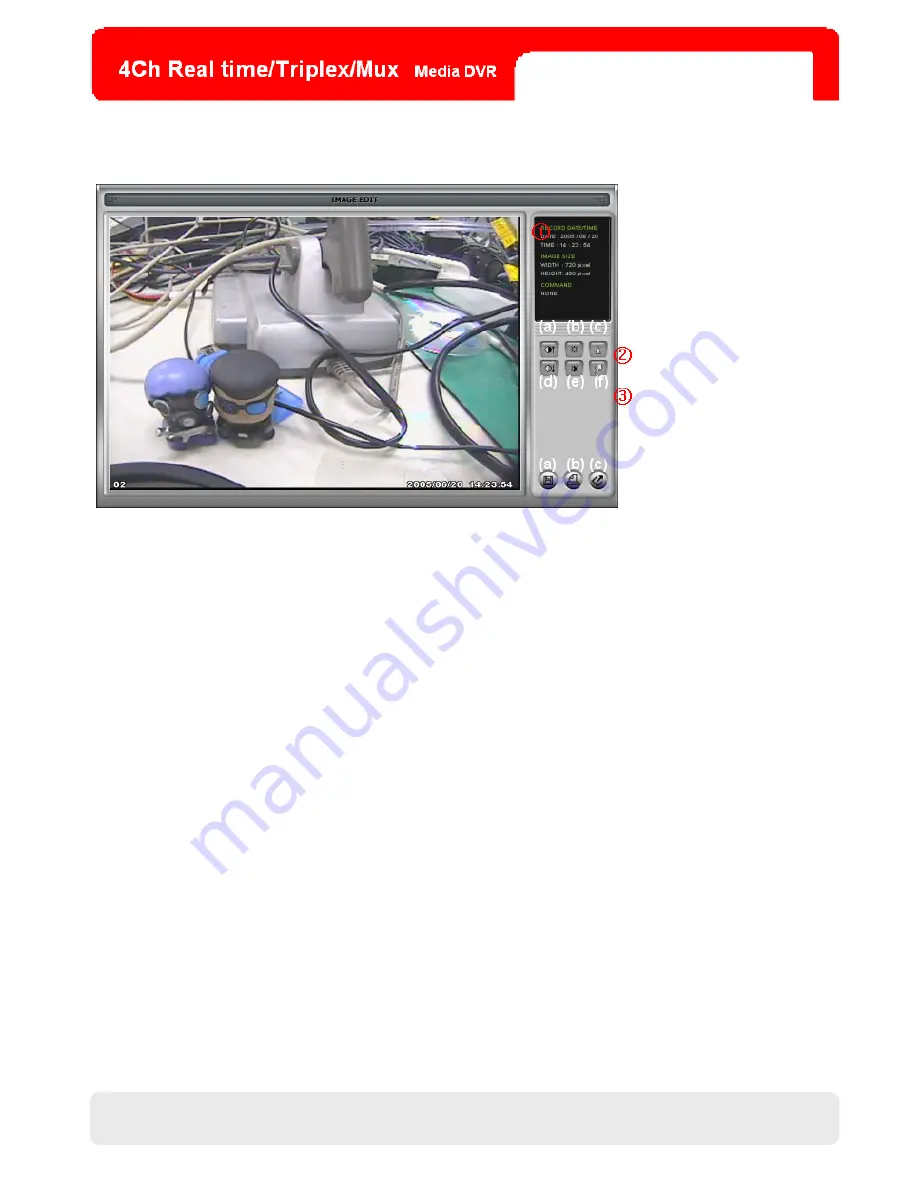
①  Image Edit Status Window

Image Edit Status Window

Image Edit Status Window

Image Edit Status Window:    Shows the recording time/date, the image size, and the command status. 

②  Edit Button

  Edit Button

  Edit Button

  Edit Button: Users can adjust color tone of copied images using these buttons. 

      (a) Contrast Plus: Enhance light and shade of an image. 
      (b) Brightness Plus: Make an image brighter . 
      (c) Sharpness: Make an image more sharp-edged. 
      (d) Contrast Minus: Reduce light and shade of an image. 
      (e) Brightness Minus: Make an image darker. 
      (f ) Blur: Soften an image.    
③  Function button

Function button

Function button

Function button:    

      (a) Save: Users can save images, in the JPEG format, in the folder where you installed the Backup CD Player. 
      (b) Print: User can print current image user selected. 
      (c) Exit: Return to the Backup CD Player mode.   

..

(a)

.

 (b) (c)


CHAP.6 DVR Program 

Setup

Summary of Contents for LR-804J02

Page 1: ...1 1 8 TFT 4CH MJPEG Media DVR 4ch Media LCD DVR User Manual User Manual LR 804J02 LR 804J03 ...

Page 2: ...2 2 Revision Update Modified Content Editor V0 90 2007 07 19 Draft Roland V1 00 2007 08 24 Primary Release Roland Revision ...

Page 3: ...t 3 This unit should not be located in an area where it is likely to be subjected to mechanical shocks Before You Start Before You Start Before You Start Before You Start 1 Ensure the power switch is off before starting to operate the DVR 2 Do not attempt to open or remove the cabinet That may expose you to dangerous voltage or other hazards 3 Installation ought to be performed by qualified servic...

Page 4: ...personnel only The lightning flash with arrow head within a triangle is intended to inform the user that parts inside the product are a risk of electric shock The exclamation point within a triangle is intended to tell the user that important operating and servicing instructions are explained WARNING RISK OF ELECTRIC SHOCK DO NOT OPEN Installation Safeguards ...

Page 5: ...4 1 M 1 M 1 M 1 MOUSE OUSE OUSE OUSE C C C CONTROL ONTROL ONTROL ONTROL 17 17 17 17 4 4 4 4 2 DVR L 2 DVR L 2 DVR L 2 DVR LOG OG OG OG IN IN IN IN O O O OPEN PEN PEN PEN M M M MAIN AIN AIN AIN M M M MENU ENU ENU ENU 17 17 17 17 4 4 4 4 3 F 3 F 3 F 3 FORMAT ORMAT ORMAT ORMAT T T T THE HE HE HE HDD HDD HDD HDD 18 18 18 18 4 4 4 4 4 T 4 T 4 T 4 TIME IME IME IME D D D DATE ATE ATE ATE S S S SETTING ET...

Page 6: ...ETU CHAP 5 NETWORK SETU CHAP 5 NETWORK SETU CHAP 5 NETWORK SETUP P P P 33 33 33 33 5 5 5 5 1 DVR N 1 DVR N 1 DVR N 1 DVR NETWORK ETWORK ETWORK ETWORK C C C CONFIGURATION ONFIGURATION ONFIGURATION ONFIGURATION 33 33 33 33 5 5 5 5 2 S 2 S 2 S 2 STATIC TATIC TATIC TATIC IP IP IP IP 34 34 34 34 5 5 5 5 3 D 3 D 3 D 3 DYNAMIC YNAMIC YNAMIC YNAMIC IP IP IP IP 35 35 35 35 5 5 5 5 4 D 4 D 4 D 4 DYNAMIC YNA...

Page 7: ...IA EDIA EDIA EDIA T T T TYPE YPE YPE YPE P P P PLAYBACK LAYBACK LAYBACK LAYBACK F F F FORMATS ORMATS ORMATS ORMATS 58 58 58 58 7 7 7 7 3 I 3 I 3 I 3 INTRODUCTION OF NTRODUCTION OF NTRODUCTION OF NTRODUCTION OF O O O ON N N N S S S SCREEN CREEN CREEN CREEN D D D DISPLAYS ISPLAYS ISPLAYS ISPLAYS 59 59 59 59 7 7 7 7 4 S 4 S 4 S 4 SETUP ETUP ETUP ETUP M M M MENU ENU ENU ENU 61 61 61 61 APPENDIX APPEND...

Page 8: ... monitors or searches using the remote viewer via the network Playback Playback Playback Playback To search and replay by the percent date time or events of the recorded video data Multiple forward playback speeds X 2 4 8 16 32 fast playback X 1 16 1 8 1 4 1 2 slow playback Multiple backward playback speeds X 2 4 8 16 32 fast playback X 1 16 1 8 1 4 1 2 slow playback Data Backup Data Backup Data B...

Page 9: ...dia DVR 5 Software CD Contains 1 manuals English Chinese 2 quick guide English 3 software tools 4 README 6 Mouse Controls all functions of the Media DVR 7 Remote Controller IR Remote Controller for Media Player 8 Screws X4 Fix an HDD to the HDD drawer 9 Audio Cable Connects left and speakers 10 BNC Adapter BNC to RCA Video Adapter 1 Main Unit 6 Mouse 3 Power Adapter 4 Quick Guide 7 Remote Controll...

Page 10: ...s 3 Receiver IR Port Receives IR signals out of the remote controller 4 Power LED Gives red light when the power is on 5 Control Buttons Control the OSD menu of the LCD DISPLAY LCD Power Switch On Off SOURCE Video Source Switch DVR MEDIA MENU Open OSD menu for LCD adjustment UP Move up Increase values or volume DOWN Move down Decrease values or volume 5 1 2 2 4 3 CHAP 2 Outlook ...

Page 11: ...s a SPOT monitor 9 CH 1 4 Connect cameras 10 HDD Drawer For HDD Combination 1 The jumper must be master 2 The HDD is expandable to 500 GB 11 ETHERNET Connects the Ethernet 12 MEDIA VEDIO OUT Connects a monitor for the Media Player 13 FUNCTION Function Port for External Devices 1 2 For External Devices eg Speed Domes 3 5 For Sirens Relay Output 14 Function Port Note 6 10 For Inputs of 4 Alarms 15 F...

Page 12: ...2 2 2 2 2 3 3 3 3 Side Side Side Side No Items Function 1 DVD Driver For Media Player Only CD VCD DVD 2 SD Slot For Media Player Only SD Card MMC Card 1 2 CHAP 2 Outlook Item 1 and 2 are for LR 804J02 only ...

Page 13: ...nstallation CHAP 3 Installation CHAP 3 Installation CHAP 3 Installation 3 3 3 3 1 Installation Configuration 1 Installation Configuration 1 Installation Configuration 1 Installation Configuration CHAP 3 Installation ...

Page 14: ...to the list of all supported HDDs in the appendix on the page 65 for information of HDDs compatible with this DVR 2 To know the maximal recording time for various HDDs please use the table of HDD recording time on the pages 66 and 67 as reference 3 The screws for the HDD are attached in the package 2 CAMERA 2 CAMERA 2 CAMERA 2 CAMERA Connect a camera to a video input CH1 4 on the rear panel of the...

Page 15: ...r combined with the video output jack MONITOR displays the identical images to the DVR s 2 A monitor combined with the video output jack SPOT sequentially displays the images of each connected channel 4 4 4 4 P P P PO O O OWER WER WER WER Connect the DC plug of the power adapter into the DC input jack of the DVR VIDEO A IN OUT VIDEO C IN OUT VIDEO B IN OUT CHAP 3 Installation Rear View of A Monito...

Page 16: ...tion Pin 6 Connects the ground wires of the connected alarm sensors ALARM D1 4 Function Pin 7 10 ALARM D1 4 Function Pin 7 10 ALARM D1 4 Function Pin 7 10 ALARM D1 4 Function Pin 7 10 Connect alarm sensors NOTE NOTE NOTE NOTE 1 The DVR affords multiple sirens 2 The DVR affords up to 4 PTZ cameras 2 2 2 2 ETHERNET ETHERNET ETHERNET ETHERNET JACK JACK JACK JACK For LAN or WAN connection 3 3 3 3 MEDI...

Page 17: ... administrator ADMIN and input the password PW composed of up to 8 digits 3 To exit click EXIT As for MAIN MENU refer to the page 23 NOTE NOTE NOTE NOTE 1 The USER ID is unchangeable and fixed as an administrator ADMIN 2 The password default is none When logging in for the first time please straightly click ENTER 3 If the inputted password matches the one you already set you will be allowed to ent...

Page 18: ...me Date Setting If the DVR is operated for the first time please set the time and date in TIME DATE SETUP MAIN MENU CONFIGURATION TIME DATE SETUP to accord with the time zone of your location HDD MANAGEMENT CAMERA SETUP MOTION SETUP ALARM SETUP INTERVAL SETUP TIME DATE SETUP PASSWORD SETUP BUZZER SETUP ESC MODEL SERIAL BLOCKS SIZE SPEED OVERWRITE FORMAT ESC DATE TIME DATE FORMAT HOUR FORMAT MONTH ...

Page 19: ... Recording Recording Mode Mode Mode Mode PTZ HDD Status HDD Status HDD Status HDD Status PlaybackMode PlaybackMode PlaybackMode PlaybackMode Amount of Displayed Data PlaybackToolbar PlaybackToolbar PlaybackToolbar PlaybackToolbar Separated Forward Playback x 1 4 1 2 Time Backward Playback Pauses Forward Playback Separated Backward Playback x 1 4 1 2 Time Speed Up Playback x 2 4 8 16 32 Times Speed...

Page 20: ...lick PLAY EVENT SEARCH Searches via the event list that covers all events of motion detection alarm input and video loss The DVR will replay the targeted event from when it occurred NOTE NOTE NOTE NOTE Recorded images in different modes alarm recording motion recording and continuous recording are successively accumulated in chronological order SEARCH PERCENT SEARCH TIME DATE SEARCH EVENT SERACH E...

Page 21: ...icture Picture in Picture Picture in Picture Click in the full screen mode and you will see a small window in the lower right position When one of the four channels is displayed on the main screen others will switch sequentially in this window You can set their channel switching interval in PIP SCREE MAIN MENU CONFIGURATION INTERVAL SETUP PIP SCREEN 6 PTZ PAN TILT ZOOM 6 PTZ PAN TILT ZOOM 6 PTZ PA...

Page 22: ... is full of recorded images with overwriting off 2 A user is backuping recorded images via the USB slot 3 A user is updating a firmware via the USB slot 4 HDD MANAGEMENT is being opened 8 8 8 8 F F F FULL ULL ULL ULL 4 4 4 4 SPLIT SPLIT SPLIT SPLIT S S S SCR CR CR CREEN EEN EEN EEN 1 In a full screen mode if you click shown on the left half of the toolbar the screen will be altered to a 4 split sc...

Page 23: ...POSITON Alter the position of the main screen horizontally BORDER ENABLE Enable or disable the borders for the 4 split screens BORDER WIDTH Adjust the border width BORDER COLOR Change the border color NOTE NOTE NOTE NOTE In each setting menu click DEFAULT to restore all altered parameters on the menu to the factory default 2 OSD SETUP 2 OSD SETUP 2 OSD SETUP 2 OSD SETUP TOP OSD OFFSET Alter the po...

Page 24: ...o restore all changed parameters of the 4 channels on the menu to the factory default 2 For more transmitted images and longer recording time via IP network set the resolution as 352x240 and the quality as LOW or NORMAL 3 Transmitting size of images in the PAL system is a little bigger than that in the NTSC system but the total recording time for both systems is the same 4 To know the maximal reco...

Page 25: ...ion MOTION ALARM Records once receiving alarm signals or detecting motion ALL Set the entire grid 24 hours a day 7 days a week as the designated recording mode in TYPE DATE Click a day on the menu to set 24 hours of that day as the designated recording mode HOUR Click an hour on the menu to make the DVR record in the designated recording mode during this hour everyday NOTE NOTE NOTE NOTE 1 Each ty...

Page 26: ...hich determines the transferring rate between the DVR and the HDD OVERWRITE Enable or disable overwriting the HDD when it is stuffed with recorded images If it is enabled the original recorded data will be replaced by new images Oppositely the DVR will cease recording if the function is switched off FORMAT Click it to remove all the recorded images by formatting the HDD NOTE NOTE NOTE NOTE 1 While...

Page 27: ...ection DURATION Set the recording time after a camera detects any motion DETECT CELL NUMBER Determine the minimal cells blocks in the grid that activate a motion event MOTION DETECTION GRID Determine the coverage of motion detection On this grid press the left button and drag the cursor to disable cells to detect motion To enable them use the right button NOTE NOTE NOTE NOTE A camera must be sched...

Page 28: ... or in the PIP small window can be switched in this menu SEQUENCE SCREEN Set the switching interval of channel sequence in the live full screen PIP SCREEN Set the switching interval of channel sequence in the PIP window EVENT UPDATE Set the event update duration in the list of EVENT SEARCH NOTE NOTE NOTE NOTE On condition that a user sets the event update duration as 100 seconds when the DVR detec...

Page 29: ...n item on the left side USER PW NEW PW CONFIRM first to activate the corresponding input space Then input a password via the number bar and click ENTER to affirm it 2 The password default is none For security reasons changing the password is highly recommended 8 8 8 8 BUZZER SETUP BUZZER SETUP BUZZER SETUP BUZZER SETUP KEY TONE Switch on off all clicking sounds VIDEO LOSS Switch on off the caution...

Page 30: ... DDNS SETUP B DDNS SETUP DDNS ENABLE Enable or disable the DDNS function DNS SERVER Set the IP address of the DNS server INTERVAL Set the connection time between the DVR and the DDNS server D Days H Hours M Minutes DDNS STATUS Indicates whether the DVR is registered to the DDNS server IP ADDRESS Indicates the IP address of the DVR IP PORT Indicates the IP port of the DVR REMAIN TIME Indicates the ...

Page 31: ...Set the switching interval of the SPOT monitor ALARM POPUP With this function on once receiving alarm signals from any channel the DVR will enable the SPOT monitor to cease channel sequence and display the live images of this channel MOTION POPUP With this function on once detecting motion from any channel the DVR will enable the SPOT monitor to cease channel sequence and display the live images o...

Page 32: ...t a size for backup images BACK UP Click it to launch backup process 6 6 6 6 F F F FIRMWARE UPGRADE IRMWARE UPGRADE IRMWARE UPGRADE IRMWARE UPGRADE CURRENT VER Depicts the current firmware version of the DVR UPGRADE VER Depicts the upgrade firmware version the DVR detects in the USB mass storage device Users have to execute CHECK USB first CHECK USB Click it to detect the upgrade version of the fi...

Page 33: ... a DSL provider does you MUST have a router installed and follow instructions in 5 4 Dynamic IP of PPPoE DSL on the page 36 for DVR setup and access 2 Please verify the Internet access after installing any new equipment a router a switch a modem etc TCP IP Setting TCP IP Setting TCP IP Setting TCP IP Setting of your PC of your PC of your PC of your PC Before configuring the DVR please fill out the...

Page 34: ...Connect an LAN cable to the DVR after confirmation 3 Go to IP SETUP of the DVR and set DHCP MODE as MANUAL 4 Verify if MAC ADDRESS starts from 00 0A A2 5 Set IP ADDRESS assigned from the ISP 6 Set IP PORT 50000 is recommended 7 Set GATEWAY assigned from the ISP 8 Set SUBNET assigned from the ISP 9 Go out of MAIN MENU 10 Turn off and on the modem router the ISP provides to reset clients of MAC from...

Page 35: ...he DVR 2 Connect an LAN cable to the DVR after confirmation 3 Turn off and on the modem router the ISP provides to reset clients of MAC from the ISP Users need to wait for 30 seconds after turning on 4 Verify MAC ADDRESS starts from 00 0A A2 5 Set DHCP MODE as AUTOMATIC Then click IP DETECT to get a dynamic IP 6 Go out of MAIN MENU after getting the IP successfully 7 Access the DVR via the Remote ...

Page 36: ...e connecting the DVR 2 Connect the router to a DSL modem as the flow chart shown below 3 Set the Internet connection of the router Refer to the router manual 4 Verify the router s network sub group is correct 5 Connect the DVR to the router 6 Set DHCP MODE as MANUAL in IP SETUP MENU EXTERNAL DEVICE TCP IP SETUP IP SETUP 7 Verify MAC ADDRESS starts from 00 0A A2 8 Input an internal IP address assig...

Page 37: ...server server server 1 To connect the DVR via the Internet registration to the DDNS web server is necessary Please access www j2kip com first In this homepage click Member Register to create a member ID After filling up the form and confirmation a message of Success will show and you will be automatically returned to the previous page 2 Please click Login in the upper right corner to enter My DVR ...

Page 38: ...38 3 Please click Confirm after filling out this form shown as below 4 Now some information of the DVR is listed on the DDNS web server short of the IP address and the port number CHAP 6 DVR Program Setup ...

Page 39: ...NABLE as ON and an IP address will be automatically assigned to DNS SERVER from the DHCP server After that click REGISTER to renew the IP registered in DDNS SERVER MAC ADDRESS 00 0A A2 00 00 00 DHCP MODE AUTOMATIC IP DETECT IP PORT 50000 IP ADDRESS 192 168 001 160 GATEWAY 192 168 001 001 SUBNET 255 255 255 000 DEFAULT ESC IP SETUP DDNS ENABLE ON DNS SERVER 192 168 063 001 INTERVAL D 00 H 00 N 20 R...

Page 40: ...t the DDNS server automatically fetch your DVR s IP address and port number NOTE NOTE NOTE NOTE Prior to using the Web Viewer please add www j2kip com into Trusted Sites first as illustrated below Tools Internet Options Security Trusted Sites Sites IP Port automatically fetched Refresh it CHAP 6 DVR Program Setup ...

Page 41: ...41 41 CHAP 6 DVR Program Setup ...

Page 42: ...he IE 1 Please click to execute DVR WEB VIEWER as following illustration NOTE NOTE NOTE NOTE 1 If ActiveX control installation is required in the first access please click Yes 2 Users can also execute this program by clicking the file named RemoteWeb html in the software CD 2 Later DVR WEB VIEWER will pop up Please click CONNECT to see live images CHAP 6 DVR Program Setup ...

Page 43: ...43 43 3 The live images are displayed as below CHAP 6 DVR Program Setup ...

Page 44: ...e DVR BACKUP PLAYER click shown as below NOTE NOTE NOTE NOTE 1 If ActiveX control installation is required in the first access please click Yes 2 Users can also execute this program by clicking the file named WebPlayer html in the software CD 2 Following that BACKUP PLAYER will pop up Please click OPEN to select files 3 Select a backup image file and then click Open to replay recorded images CHAP ...

Page 45: ...45 45 4 You can see the recorded images shown as below CHAP 6 DVR Program Setup ...

Page 46: ...s to backup recorded images via the IE 1 Go to www j2kip com and click DVR Web Backup on the left NOTE NOTE NOTE NOTE Users can also execute this program by clicking the file named WEB_BACKUP html in the software CD 2 To execute backup via the network input the IP address as well as the network port and then click Connect Test CHAP 6 DVR Program Setup ...

Page 47: ...one a message of Success Connect Test will show Then click Lock to set backup time 4 Now please set well Recorded Start Time Recorded End Time Save File Path and Maximum Save File Size Right after that click Apply CHAP 6 DVR Program Setup ...

Page 48: ...48 48 5 Next click Start Backup to start recording images Finally you can review the backup files via the path you have already determined CHAP 6 DVR Program Setup ...

Page 49: ...u currently see is highlighted C C C CHANNEL HANNEL HANNEL HANNEL Select a channel if connected that you want to see in the full screen mode S S S STATUS WINDOW TATUS WINDOW TATUS WINDOW TATUS WINDOW Displays the current time and date of the program You will also see the current connection status S S S SEQUENCE SETTING PLAYBA EQUENCE SETTING PLAYBA EQUENCE SETTING PLAYBA EQUENCE SETTING PLAYBACK C...

Page 50: ... DDRESS DDRESS Input an IP address set in the DVR PORT PORT PORT PORT Input the port set in the DVR USER USER USER USER ID ID ID ID Input the ID set in the DVR Please input admin a fixed parameter P P P PASSWORD ASSWORD ASSWORD ASSWORD Input the password set in the DVR IP List IP List IP List IP List Shows all IP addresses users have inputted manually Select Select Select Select Select an IP addre...

Page 51: ...rver Save Save Save Save Save the member ID and the name Load Load Load Load Search for a member ID name saved in the Remote Viewer User ID User ID User ID User ID Input the ID set in the DVR Please input admin a fixed parameter Password Password Password Password Input the password for the DVR Connect Connect Connect Connect Receive the IP address and the port for the DVR from the DDNS server CHA...

Page 52: ... ype ype Select the PTZ camera type connected to the DVR PTZ Baud PTZ Baud PTZ Baud PTZ Baudr r r rate ate ate ate Enter the baud rate of your PTZ camera Set Path to Save Downloaded image Set Path to Save Downloaded image Set Path to Save Downloaded image Set Path to Save Downloaded image Determine the storage folder in your PC where the downloaded video clips will be stored Run in Run in Run in R...

Page 53: ...plit mode split mode View images in the 4 split mode Time Time Time Time Indicates the recording time of the image being replayed Channel selection Channel selection Channel selection Channel selection Select a camera to be replayed Time sele Time sele Time sele Time selection ction ction ction Select a time point from which the playback will be started Use the mouse to drag the point Start and en...

Page 54: ...nt images d RECORD Click this button to download playback images transmitted from the DVR to a PC Press it button light blue red and the program will start to record images Then press again to save the images during the recording period into an AVI file which can be played by Windows Media Player Calendar Calendar Calendar Calendar Select the date of the recorded images you need The outlined squar...

Page 55: ... search recorded data via these buttons a Move the slide bar to the start position b Play backward fast in a preset speed c Play backward at a normal speed d Pause e Play forward fast in a preset speed f Move the slide bar to the end position g Play forward at a normal speed F F F FUNCTION UNCTION UNCTION UNCTION 1 OPEN Open the Backup CD Player 2 EDIT Users can edit save and print recorded image ...

Page 56: ...trast Plus Enhance light and shade of an image b Brightness Plus Make an image brighter c Sharpness Make an image more sharp edged d Contrast Minus Reduce light and shade of an image e Brightness Minus Make an image darker f Blur Soften an image Function button Function button Function button Function button a Save Users can save images in the JPEG format in the folder where you installed the Back...

Page 57: ...DVR to the vendor 2 Operative 2 Operative 2 Operative 2 Operative Range Range Range Range of the Remote Controller of the Remote Controller of the Remote Controller of the Remote Controller The remote controller operates the Media Player via infrared transmission To make the remote controller function well please direct it toward the receiver infrared port on the front panel of the DVR Without bar...

Page 58: ...ack to the preceding track or scene during playback Next Go to the next chapter track or scene during playback Stop Once Pause at the present playing point 2 or more times Stop playing Up Move up for navigating the setup menu Down Move down for navigating the setup menu Left Move left for navigating the setup menu Right Move right for navigating the setup menu Enter Execute the selected item or se...

Page 59: ...ntroduced below DVD DVD DVD DVD DVD TT 1 8 CH 1 5 00 01 39 1 3 2CH OFF OFF VCD VCD VCD VCD VCD TRK 1 1 PBC 00 42 05 CD CD CD CD CD TRK 1 25 00 42 05 SD Card MP3 SD Card MP3 SD Card MP3 SD Card MP3 CDrom TRK 1 153 00 30 27 Item Function TT Title CH Channel TRK Track Playing Time Language Dolby Subtitle Recording Off Audio Not Repeat Repeat One File Repeat One Directory Repeat All 2 Audio Selection ...

Page 60: ...selection NOTE NOTE NOTE NOTE Its OSD pattern depends on the VCD contents MP3 SD Card Menu OSD MP3 SD Card Menu OSD MP3 SD Card Menu OSD MP3 SD Card Menu OSD When an MP3 CD or an SD card with media files is inserted a play menu will automatically show as below NOTE NOTE NOTE NOTE The icon squared in black allows users to select as there exist corresponding media files music photos or movies 01 FRA...

Page 61: ...n set a password of 4 digits to lock it NOTE NOTE NOTE NOTE 1 Default password is 0000 2 Once the media player is powered off the changed password will be defaulted to 0000 6 RATING Select a film rating to limit some media playing KID SAFE G PG PG13 PG R R NC 17 ADULT 7 DEFAULT In this item press RESTORE to return all changed setting values to the default 8 EXIT SETUP Quit the menu LANGUAGE SETUP ...

Page 62: ...layed images 12 10 8 6 4 2 0 5 SHARPNESS Adjust the sharpness for the displayed images 8 6 4 2 0 DIGITAL SETUP DIGITAL SETUP DIGITAL SETUP DIGITAL SETUP 1 OP MODE Select a standard digital audio setting or the older RF digital input LINE OUT RF REMOD 2 DYNAMIC RANGE When OP MODE is set as LINE OUT select this mode to adjust the effect of dynamic compression FULL 6 8 4 8 2 8 OFF 3 DUAL MONO Select ...

Page 63: ...Recording Quality Recording Quality Lowest Low Normal High Highest Playback Mode Playback Mode Playback Mode Playback Mode Percent Time and Date Event Search Playback Playback Playback Playback Playback Speed Playback Speed Playback Speed Playback Speed Forward Backward 1X 2X 4X 8X 16X 32X 1 2X 1 4X 1 8X 1 16X Sensor Input Sensor Input Sensor Input Sensor Input 4 NO NC Selectable Alarm Output Alar...

Page 64: ... Player DVD Player DVD Player Media Type Media Type Media Type Media Type DVD 5 DVD 9 DVD 10 DVD 18 DVD R RW DVD R RW CD CDR RW N A Video Input Video Input Video Input Video Input BNCx4 For Cameras Input Video Input Form Video Input Form Video Input Form Video Input Form NTSC or PAL Video Output Video Output Video Output Video Output BNCx2 Monitor Spot RCAx1 Media Video Output BNCx2 Monitor LOOP S...

Page 65: ... Dimensions Supported HDD Supported HDD Supported HDD Supported HDD Type Type Type Type Capacity GB Capacity GB Capacity GB Capacity GB Model Number Model Number Model Number Model Number 160 ST3160812A 200 ST3200822A 250 ST3250824A 300 ST3300622A Seagate 500 ST3500641A 160 WD1600JD 00GVC0 200 WD2000BB 22KEA0 250 WD2500JB 00GVC0 Western Digital 300 WD3000JB 00KFA0 Appendix ...

Page 66: ...82 5 0 455 37 414 59 375 38 323 00 280 58 3 0 758 96 690 99 625 63 538 33 467 64 2 0 1138 43 1036 48 938 44 807 49 701 46 NTSC NTSC NTSC NTSC 704x240 704x240 704x240 704x240 1 0 2276 87 2072 97 1876 88 1614 99 1402 92 Recorded Images Quality Recorded Images Quality Recorded Images Quality Recorded Images Quality KB KB KB KB LOWEST LOW NORMAL HIGH HIGHEST Recorded Images Recorded Images Recorded Im...

Page 67: ...78 70 496 03 3 0 1361 66 1218 32 1102 29 964 51 826 72 2 0 2042 48 1827 49 1653 44 1446 76 1240 08 NTSC NTSC NTSC NTSC 352x240 352x240 352x240 352x240 1 0 4084 97 3654 97 3306 88 2893 52 2480 16 Recorded Images Quality Recorded Images Quality Recorded Images Quality Recorded Images Quality KB KB KB KB LOWEST LOW NORMAL HIGH HIGHEST Recorded Images Recorded Images Recorded Images Recorded Images Fr...

Page 68: ...GRAY DARK GRAY BLACK WHITE LIGHT GRAY TOP OSD OFFSET 10 9 1 DISPLAY SETUP OSD SETUP BOTTOM OSD OFFSET 10 9 1 CHANNEL CH1 4 RESOLUTION 352X240 704X240 NTSC 360x288 720x288 PAL QUALITY LOWEST LOW NORMAL HIGH HIGHEST RECORDE SETUP FRAME RATE 30 0 15 0 10 0 7 5 6 0 5 0 3 0 2 0 1 0 NTSC 25 0 12 5 8 3 6 2 5 0 4 1 3 5 2 0 1 0 PAL CHANNEL CH1 4 TYPE CONTINUE MOTION ALARM MOTION AL ARM ALL Execution 0 23 H...

Page 69: ...MIN USER PW 8 digits NEW PW 8 digits PASSWORD SETUP CONFIRM 8 digits KEY TONE ON OFF VIDEO LOSS ON OFF ALARM ACTIVE ON OFF CONFIGURATIION BUZZER SETUP MOTION DETECT ON OFF MAC ADDRESS Indication DHCP MODE MANUAL AUTOMATIC IP DETECT Execution IP PORT 5 digits 00000 65535 IP ADDRESS 4 sets of 3 digits 000 255 GATEWAY 4 sets of 3 digits 000 255 IP SETUP SUBNET 4 sets of 3 digits 000 255 DDNS ENABLE O...

Page 70: ...PAN SPPED 0 7 1 TILT SPEED 0 7 1 PAN TILT SETUP SPEED SETUP ZOOM SPEED 0 7 1 SWITCHING INTERVAL 01 99 SEC 1 ALARM POPUP ON OFF MOTION POPUP ON OFF EXTERNAL DEVICE SPOT SETUP EVENT POPUP DURATION 01 99 SEC 1 START Indication HDD END Indication PARTITION Partition Selection START Indication END Indication MEDIA SIZE 010 700 MB 10 BACK UP USB SETUP BACK UP Execution CURRENT VER Indication UPGRADE VER...

Reviews: