EverSewn sew&go 1 Repair Manual Download Page 22

21


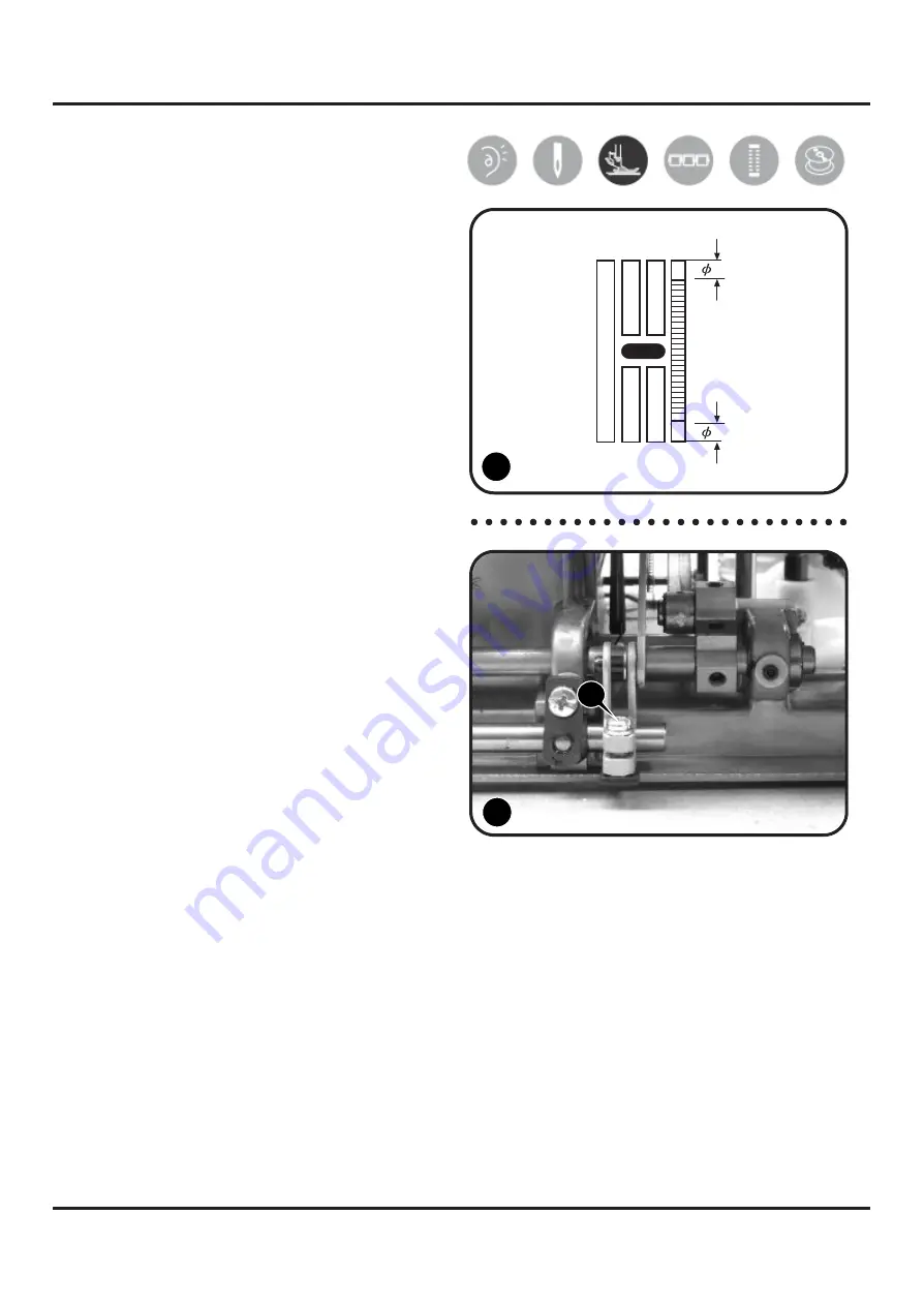
5-18  Position  of  the  feed-dog    in 

relation  to  the  needle  plate 
(front  to  back) 


1)  Remove  the  free  arm  cover,  base  plate 

and set the stitch length dial to "4".


2)  Turn  hand  wheel  to  move  feed-dog 

forward and backward.


3)  Feed-dog   must   have   clearance   along 

the  whole  length  of  feeding  movement. 
It must at no time touch the needle plate. 
(1)


4)  Otherwise, adjust feed rock crank screw. 

1


5)  Loosen  screw  (a)  of  feed  rock  crank.


Moving feed-dog forward/backward until 
reaching to the center position. (2)


6)  Tighten screw (a) after adjustment.


a


2


 a 

Summary of Contents for sew&go 1

Page 1: ...Repair Manual sparrow 15 series...

Page 2: ...aft gear 18 5 15 Feed cam position adjustment 19 5 16 Feed lifting rock cam position adjustment 19 5 17 Feed dog height 20 5 18 Position of the feed dog in relation to the needle plate front to back 2...

Page 3: ...ke up lever Slit type Presser foot lift Two steps type Needle threader Manually Auto type Auto type Needle plate Screw fixing type Upper thread tension adjust device Top of upper plate inclusive turni...

Page 4: ...3 2 Out Look...

Page 5: ...n wider stopper 10 Stitch width dial for sew go 5 11 Stitch length dial 12 Pattern selector dial 13 One step buttonhole lever for sew go 5 14 Automatic threader optional 15 Horizontal spool pin 16 Bob...

Page 6: ...rew b and the free arm cover 4 3 Base plate Lay down machine Remove 4 screws c d e f Remove the base plate c d Base plate e f 3 4 4 Back cover Remove the face plate cap free arm cover and base plate f...

Page 7: ...rew l about 3mm m 5 Remove the screw m which deeply inside the machine n 6 Remove the pattern selector dial Remove the front cover following direction of arrow Pattern selector dial Front cover 7 l m...

Page 8: ...n winding problem 5 2 Play of arm shaft 1 Remove the face plate free arm cover base plate back cover front cover and loosen screws a b of arm shaft collar A 1 2 Pull hand wheel backward b B A 3 Push a...

Page 9: ...ttern cam gear s movement 4 The insufficient tightness could be re adjusted by following steps 1 2 5 Re confirm needle flow after above adjustment is necessary 5 4 Drop middle point of needle 1 Remove...

Page 10: ...ew a of presser bar bracket with the hexagon screwdriver 3mm 1 3 Place gauge B 6 0 6 2mm on top of needle plate 2 A a 4 Lift up presser bar lifter lever so bottom of presser foot and top surface of ga...

Page 11: ...te should be 3 5mm 1 5mm 3mm 3mm 5mm 4 If needle flow is less than 3mm loosen arm shaft worm screw a and turn arm shaft worm A toward back 2 5 If needle flow is more than 6mm turn arm shaft worm A tow...

Page 12: ...cover first 2 Set pattern selector dial to stitch width dial for 3 dial model 3 Loosen screw a than adjust screw unit b 1 4 clockwise needle moves left a counter clockwise needle moves right b Make s...

Page 13: ...maximum zigzag width 3 Loosen nut a of the screw b 1 4 Adjust needle by turning clockwise counter clockwise screw b a b 5 Make sure needle drops on left right of needle hole with even distance to the...

Page 14: ...mm into the center of the hook 1 4 Set needle at its lowest point stop at the position whan point of the needle across the edge of the gauge 1 5 Loosen screw a 2 6 Adjust height of needle by moving ne...

Page 15: ...eader stopper 1 0 1mm Threader hook 3 Adjust the stopper 2 Remove face plate and turn hand wheel to raise needle bar to its highest position Loosen screw a of the threader stopper 1 A Threader hook Mo...

Page 16: ...needle and shuttle A hook will agree with 4 Loosen screws a b of open shuttle race 2 5 Move shuttle race B upward downward to adjust movement 2 1 Upward tighten the distance Downward lengthen the dis...

Page 17: ...ts lowest point when it swings to left a 5 Loosen another screw b of crank connecting rod crank 1 6 Turn shuttle driver A to adjust timing of needle and hook 2 1 7 Tighten two screws of crank connecti...

Page 18: ...ng rock cam A to right 1 A 2 Push lower shaft gear B to left tightly against shuttle driver shaft gear complete C 2 a 3 Push feed lifting rock cam A back toward left and secure it tightly 1 4 Avoid ov...

Page 19: ...le In this position face cut facing side of shuttle driver shaft to front 2 1 4 Re assemble back shuttle driver shaft gear align shuttle driver shaft gear and lower shaft gear B to mesh with each othe...

Page 20: ...A a shaft position Make sure hair line marking on feed cam A match correctly with marking of arm shaft B B 5 16 Feed lifting rock cam position adjustment Problems associated with delivery amount stitc...

Page 21: ...plate The feed dog height then can be checked 1 4 Press reverse botton At the correct height 0 9mm the feed dog will be moved freely forward and backward 5 Turn screw a of feed rock crank 1 clockwise...

Page 22: ...and wheel to move feed dog forward and backward 3 Feed dog must have clearance along the whole length of feeding movement It must at no time touch the needle plate 1 4 Otherwise adjust feed rock crank...

Page 23: ...in relation to the needle plate left to right 1 Remove the face plate free arm cover base plate and back cover 2 Loosen screws a b Move feed dog left right to middle position 3 Tighten screws a b afte...

Page 24: ...ake measurement 1 3 Put dial tension thread into gauge s hook and pull and the standard range should be 60 80g 4 If the range is not between 60 80g adjust tension by turning plastic dial a forward bac...

Page 25: ...e bobbin case tension gauge A and test its tension a The standard tension should be 25 40g 2 If not adjust by turning screw a clockwise counter clockwise 1 Clockwise stronger Counter clockwise weaker...

Page 26: ...on gauge A Its standard measurement should be 200g 1 A 2 Adjust tension by loosening screws a b of motor bracket B 2 3 Lift motor bracket upward downward to adjust belt tension Upward weaker 1 Downwar...

Page 27: ...over front cover 2 Set pattern selector dial to 3 Set stitch length dial at S1 4 If the patterns are too close adjust by turning screw a b anti clockwise 1 2 If the patterns are too open adjust by tur...

Page 28: ...ing the selector dial at and then the left side by setting at for 1 3 series 4 Set the stitch length dial at 0 5 to 1 5 To sew by using thread in effect to confirm delivery amount of forward and backw...

Page 29: ...to for 5 series 4 Set the stitch length dial at 0 5 to 1 5 While buttonhole upper or lower stitching remain the same distance tacking without delivering cloth 1 1 If cloth delivered forward adjust sc...

Page 30: ...f bobbin winding When the lower part of bobbin winding is thicker turn the screw a of threader guide counter clockwise 2 When the upper part of bobbin is thicker turn the screw a of threader guide clo...

Page 31: ...Voltage 230V Voltage 120V...

Reviews: