background image


EHN7221/7260/7360 

65


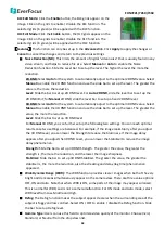
Notification Over: 

Select the desired notification types from the following items. 


Log: 

Check the box if you want the camera to list the event’s details in its log if the event is 

triggered. 


Trigger Alarm Output Duration Time  


  second:

 Check if you want the camera to relay the 

event reaction to a device attached to the alarm relay output wire and then set up the alarm 
output duration time (between 10 and 120 seconds). 


Send Mail Notification: 

Check the box if you want the camera to send an email text notification 

and one image file to the email address entered in the SMTP Settings field (see 

7.3.3 

Notification

). 


Upload to FTP: 

Check the box if you want the camera to upload the recordings to the FTP 

server entered in the FTP Repository Settings (see 

7.3.3 Notification

). 


Record to micro SD Card: 

Check the box if you want the camera to start recording its video feed 

(when the event occurs) on an on-camera micro SD Card (if such a card has been inserted). 
 

Note: 

The recording will only be as long as the combined Pre- and Post-trigger Buffers, so 

make sure you enable at least one of these buffers, especially the Post-trigger Buffer. 


Record to PC: 

Check the box if you want the camera to start recording its video feed (when the 

event occurs) on PC.


Network Alarm: 

Check the box if you want the camera to send a network alarm signal (when 

the event occurs) to the CMS servers. Note that you have to configure the Network Alarm 
Settings for this function to work (see 

7.3.3 Notification

). 


IR cut filter:

 Check the box if you want the camera to turn ON / OFF the IR cut filter (when the 

event occurs). 


Note: If you enable the Notification Over “IR cut filter ON / OFF” function, the camera will 
switch Day / Night mode based on the Event Trigger Type setting. 


:

 Set up the Event information and click the 

Create

 button, the created Event information 

will be listed in the Event List. 

:

 Highlight an item in the Event List and then click the 

Remove

 button to remove the 

highlighted item. 

:

 Highlight an item in the Event List and edit the Event information on the left-side. Click 

the 

Apply 

button to save the settings. 

Click the button to cancel the changes and return to the previous settings. 


Summary of Contents for POLESTAR EHN7221

Page 1: ...Star Light Outdoor Dome IR Network Camera EHN7221 7260 7360 Ultra Low Light Network Camera User s Manual Copyright EverFocus Electronics Corp Release Date March 2016 ...

Page 2: ...of this manual may be reproduced or transmitted in any form or by any means without written permission of the EverFocus Electronics Corporation EverFocus 12F 1 No 79 Sec 1 Shin Tai Wu Road Hsi Chih New Taipei City Taiwan TEL 886 2 2698 2334 FAX 886 2 2698 3943 www everfocus com tw March 2016 ...

Page 3: ...r in a particular installation If this equipment does cause harmful interference to radio or television reception which can be determined by turning the equipment off and on the user is encouraged to try to correct the interference by one or more of the following measures Reorient or relocate the receiving antenna Increase the separation between the equipment and receiver Connect the equipment int...

Page 4: ...ric shock or in extreme cases fire 6 Cleaning For cameras with interchangeable lenses do not touch the surface of the sensor directly with the hands Use lens tissue or a cotton tipped applicator and ethanol to clean the sensor and the camera lens Use a damp soft cloth to remove any dirt from the camera body Please do not use complex solvents corrosive or abrasive agents for cleaning of any part of...

Page 5: ...er 17 5 3 Connecting the Camera to the Network 18 5 4 Live View Window 20 6 Playback 26 6 1 Remote Playback Using Playback Page 26 6 2 Setting up the Playback Function 28 6 2 1 Inserting Removing the micro SD Card 28 6 2 2 Testing the Playback Function 29 7 Settings 31 7 1 System Settings 32 7 1 1 Network 32 7 1 2 Date Time 38 7 1 3 Storage 39 7 1 4 Display and Overlay 41 7 1 5 System Maintenance ...

Page 6: ...7 3 2 Event 63 7 3 3 Notification 68 7 4 Link to Smart Phone App 71 8 Upgrading Firmware Using IP Utility 72 9 Specifications 74 10 Troubleshooting 76 Appendix 81 A Tested Card Brands 81 B Enabling the Multicast Function 82 C RTSP URL Syntax 84 D Setting up Port Forwarding Function 85 E Setting up DDNS Function 87 ...

Page 7: ...or surveillance The POLESTAR Series outdoor IP dome camera conforms to ONVIF for compatibility with other network video devices You can also use EverFocus Mobile applications to remotely view the live views of the cameras through your iOS or Android handheld devices or use EverFocus CMS to remotely manage multiple IP devices connected on the network The POLESTAR Series outdoor IP dome camera Model...

Page 8: ...rminal Block 3 LAN PoE Connect to a 10 100 Ethernet or PoE 4 Micro SD SDHC Slot Insert a micro SD SDHC card see Appendix for tested card brands 5 Reset Button Press and hold the Reset Button for 10 seconds to reset all configurations to the factory default settings 6 IR LEDs 33 IR LEDs for infrared illumination in night vision applications 7 Lens Vari focal lens Auto Focus 3 3 10mm F1 3 P IRIS 8 L...

Page 9: ... Corridor Format True Day Night function 3D Noise Reduction for Low light Conditions 3DNR Extended IR range of up to 30M 98 4ft with 33 LEDs Smart IR function eliminates overexposure problems Wide dynamic range function WDR Two way audio Defog function supported RS 485 supported Alarm I O supported Micro SD card supported Triple power inputs supported PoE 12VDC 24VAC IP68 water proof and IK10 vand...

Page 10: ...45 Connector x 1 Phillips Screw x 4 Base Plate x 1 Screw Anchor x 4 Inner Paper x 1 Rubber Ring x 1 replace the old rubber ring around Software CD x 1 the lens only when it is damaged Quick Installation Guide x 1 Note 1 Equipment configurations and supplied accessories vary by country Please consult your local EverFocus office or agents for more information Please also keep the shipping carton for...

Page 11: ...rect sunlight it is strongly recommended to use the L Shaped Mounting Bracket to mount the camera to the wall IP Sidekick IP Sidekick ESK1000 Using it for installation you do not need to pre configure the IP address or to use an additional monitor to check and adjust all the IP cameras The product can assign an IP address to the camera then you can connect and check the camera live view using Ever...

Page 12: ...rs with a built in amplifier and external power supply are required 3 2 1 6 5 4 9 8 7 12 11 10 16 15 14 13 Camera Module Pin Assignment No Functions No Functions 1 12 VDC Input 9 Audio Output Line out 2 Digital GND 10 Audio GND 3 Alarm Out Alarm Output 11 CVBS Output 4 Alarm COM 12 Digital GND 5 Alarm In Alarm Input 13 AC24V 6 Digital GND 14 AC24V 7 Audio Input Line in 15 RS485_A 8 Audio GND 16 RS...

Page 13: ...e camera on the wall where direct sunlight may occur it is strongly recommended to mount the camera using the L Shaped Mounting Bracket to prevent the camera from being damaged by direct sunlight Please refer to the Quick Installation Guide of L Shaped Mounting Bracket for more details ...

Page 14: ...nscrew the four screws and remove the cover from the camera 2 Screw the Base Plate to the Wiring Box using the supplied four Phillips Screw Base Plate Wiring Box If you want to wire the cables through the bottom of the Camera Case follow the steps below a Remove the Circle Plate on the bottom of the Camera Case You can simply loosen the Circle Plate using a coin Circle Plate Camera Case ...

Page 15: ...bottom of the Camera Case Cable Gland Camera Case c Screw the Circle Plate to the side hole on the Camera Case d Screw the Adapter Plate between the Base Plate and Wiring Box Base Plate Wiring Box Adapter Plate 3 Screw the Camera Case back to the Base Plate using the supplied four Hexagon Screws Base Plate Camera Case ...

Page 16: ...e Stopper depends on the number of cables inserted One Cable Conduit can only be inserted with one cable Plug Stopper Cable Conduit c Insert the network PoE cable through the Cable Conduit if your network PoE cable already has a RJ 45 connector then you can use the Slitted Cable Conduit Slitted Cable Conduit d Optionally insert the additional wires such as power if you want to power the camera thr...

Page 17: ...ap 5 Connect the network PoE cable to the LAN PoE port on the camera module If you have difficulty connecting the network cable to the LAN PoE port on the camera module you can unscrew these two screws and take out the camera module 6 If you have inserted additional wires connect the wires to the terminal block Please refer to 4 3 Terminal Block for pin assignment 7 Optionally insert a micro SD SD...

Page 18: ... angle Pan Adjustment Simply turn left right for the top camera module 360 Tilt Adjustment Using the two tilt screws 64 Rotational Adjustment Using the rotate screw 180 10 Screw the cover back to the camera case 11 To adjust zoom and focus please use Lens Control buttons on the Live View window Please refer to 5 4 Live View Window in the User s Manual Note Before start operating the IP camera plea...

Page 19: ...Q Support DownloadCenter_p1 aspx Support Download Center Keyword Search IP Utility Please connect the IP camera on the same LAN of your computer 1 Save IP Utility Setup exe in your computer Double click the exe file and follow the on screen instructions to install the IP Utility 2 Click the Finish button the IP Utility will be automatically launched to search the IP devices connected on the same L...

Page 20: ...ruction page will only be prompted for the first time login in order to update the system to the latest Plugin version 2 If the Error window appears please be sure to close ALL the Web browser windows first and then click Retry When the Completing the ePlayer Setup Wizard window shows up click Finish Then you can open a new browser again to access the camera s remote Web interface 6 To optionally ...

Page 21: ...pply and save the settings Note 1 Most networks uses DHCP to assign IP address if you are unsure of your network settings please consult your network administrators for configuration details 2 If you want to set up PPPoE please refer to 7 1 1 Network To set up a static IP By default EverFocus IP cameras are set up with DHCP To change the IP setting to static IP select Static IP from IP Type drop d...

Page 22: ...EHN7221 7260 7360 16 To show the Subnet Mask and Gateway items on the title bar right click the title bar to display the Customize Columns window select Subnet Mask and Gateway and then click OK 1 2 3 ...

Page 23: ...dministrator 2 You may need to turn User Account Control off if you still can t see the Remote Live View On the computer click Start Control Panel System and Security Action Center click Change User Account Control Settings the User Account Control Settings window appears Adjust the slide bar to Never Notify and then click OK Restart your computer if requested Note For Windows 8 and Windows 10 use...

Page 24: ...o see the IP camera on a LAN WAN Internet The camera must be assigned an IP address that is compatible with its LAN By setting up port forwarding on the router you can remotely access the cameras from outside of the LAN via the Internet To remotely access the Web interface of the IP camera please refer to 7 1 1 Network DDNS Settings To set up port forwarding please refer to Appendix D Setting up P...

Page 25: ...connection may require that you use DDNS for a reliable connection Please refer to Appendix E Setting up DDNS Function Cat 5 Straight Through Cable High speed modem Internet One to One Connection Directly from PC to IP Camera You can connect directly without using a switch router or modem However only the PC connected to the camera will be able to view the IP camera You will also have to manually ...

Page 26: ... SD SDHC card For this function to become active you have to insert a micro SD SDHC card into the micro SD SDHC card slot on the camera see 6 2 Setting up the Playback Function For the tested card brands please refer to Appendix A Tested Card Brands 3 Snapshot Click the Snapshot button to take a snapshot By default the snapshot will be saved at C EverFocus To change the location see Record to PC i...

Page 27: ...7 1 3 Storage Note For Microsoft IE10 and above users some settings have to be complete to enable this function see B Snapshot Record error message in 10 Troubleshooting 5 Audio Microphone Click the Audio and Microphone buttons to switch the sound on off for the speakers and microphones respectively if such external devices have been connected to the camera directly or via the network To activate ...

Page 28: ...snapshots will also be rotated Note To achieve the best 9 16 display effect it s recommended to a Install the camera sideways by rotating the camera to the left or right by 90 90 b Select a 16 9 View Size e g 1920 x 1080 1024 x 768 c Use the Rotate button 9 Video Stream Select the Video Stream Stream 1 and Stream 2 that will be displayed in the live view window on the bottom see 7 2 1 Streaming an...

Page 29: ...the live view window by enabling the Show One Push Buttons function in the Live View Layout Settings see 7 1 4 Display and Overlay White Balance To enable the button turned from faded to clear on the Setting Advanced Camera Settings Image select One Push from the mode drop down list in the White Balance Settings field and click the Apply button Once this is done clicking the White Balance button o...

Page 30: ...board the camera You can then click on the Playback button to open the Playback page and search for and play all such recordings that had been stored on the card Such event actions will be effective once they have been configured in the Event List see 7 3 2 Event Click the Reset Alarm button to reset the alarm output remotely 16 Lens Control The Lens Control buttons can be hidden on the Live View ...

Page 31: ...x or at bottom of page This shows the name of the camera that is currently active or being configured current date time and current frame rate You can activate these info displays in the Overlay Text Settings see 7 1 4 Display and Overlay 18 Event signal icons above video screen When an event is triggered a signal icon will appear at the top right of the Live View window to alert the user Alarm In...

Page 32: ... computer using VLC media player Windows Media Player 12 or other players support AVI MP4 format Note The Playback page is only accessible once the on camera micro SD card is inserted and active Please refer to Appendix A for the tested card brands 6 1 Remote Playback Using Playback Page On the Live View Window click the Playback button to open the Playback page Search by File Click the Search but...

Page 33: ...ecific file Pause Click to pause playing back Stop Click to stop playing back Snapshot Click to take a snapshot Zoom In Click to zoom in Zoom Out Click to zoom out Filename This area will display a list of search results recording files and folders If you use the Search button under the Show All Files on micro SD Card header to search folders named with the recorded date will be displayed first Cl...

Page 34: ...ard Click the Remove button Advanced tab System Settings Storage Secure Digital Card when the camera is powered on the micro SD card information micro SD card is not mounted will display and the Remove button will change to Attach and then you may remove the micro SD card If you want to insert the micro SD card again insert the micro SD card and then click the Attach button After inserting the mic...

Page 35: ...er Buffer and Record to micro SD Card For Alarm Input Manual Trigger and Tampering Detection trigger types multiple events can be created on the Event List but only one event can be enabled For example if you create three Alarm Input trigger events only one event under this trigger type can be enabled The option of Enable This Event for the rest of two Alarm Input events will be grayed out and dis...

Page 36: ...er The recording period will be as long as the buffer time you selected the default period is 10 seconds 10 Click the Playback button to open the Playback page 11 There are different ways to search for recording files on the camera s micro SD card i e the Playback memory For a recent recording like your test event simply click the Search button under the Show All Files on micro SD Card header 12 I...

Page 37: ... There are two tabs Basic and Advanced on the left side bar You can set up the basic camera settings in the Basic tab To further set up comprehensive camera settings click the Advanced tab which includes all the settings to be configured The chapters below describe the detailed information of the Advanced tab ...

Page 38: ...EHN7221 7260 7360 32 7 1 System Settings 7 1 1 Network ...

Page 39: ...cts with other network connected devices PPPoE This is a DSL connection application The ISP will ask the user to input a username and password Contact your ISP for these details IPv4 IP address When DHCP is not used the user needs to manually enter the IP address of the camera Do not enter an IP address that is already used for your computer or other network cameras Subnet Mask This field is used ...

Page 40: ...e Advanced tab DDNS Dynamic Domain Name System is a service used to map a domain name to the dynamic IP address of a network device You can set up the DDNS service for remote access to the IP camera DDNS assigns a domain name URL to the IP camera so that the user does not need to go through the trouble of checking if the IP address assigned by DHCP Server has changed Once the IP is changed the IP ...

Page 41: ...In certain router models it is possible that you will not be able to access the camera using DDNS while inside the router s network Please try using a PC located outside of your router s network Default Ports on All EverFocus IP Cameras HTTP 80 RTSP 554 HTTPS 443 3 The host name obtained from EverFocus DDNS server or other DDNS server should not include a space underline or any special characters ...

Page 42: ...ting one by clicking the Remove button to erase the certificate 5 On the Web page change the address from http to https in the address bar and press Enter on the keyboard Some Security Alert dialogs will pop up Click OK or Yes to enable HTTPS Create Certificate Request You can apply for an official certificate from an issuing Certificate Authority 1 Select Certificate Request and fill in the follo...

Page 43: ...ficate authority to issue an SSL TLS certificate and then download the issued certificate on your computer 6 In the Install Signed Certificated field click the Browse button to search for the issued certificate and then click the Upload button to import the certificate Once the certificate has been uploaded this field will show the subject line of the certificate QoS Settings This function can onl...

Page 44: ... Click Apply to save the setting Time Click time to set desired hour and minute Click Apply to save the setting NTP Server Enter the Network Time Protocol server if applicable The camera s time will be automatically adjusted by synchronizing with the NTP server Click Apply to save the setting Time Zone Setting Set the time zone of the camera s location Click Apply to apply the changes or Cancel to...

Page 45: ...Check the box for overwriting recording snapshot file when the disk storage capacity is full The user can set the storage capacity limitation in the in sentence box below the Enable Overwrite setting If the remaining hard disk capacity is less than MB 50 2000 Click Apply to apply the changes or Cancel to cancel the changes and return to the previous settings Secure Digital Card This function excep...

Page 46: ...e 6 2 1 Inserting Removing the micro SD Card Format For the first time user click to format the card All data saved on the micro SD card will be removed if the card is formatted see 6 2 1 Inserting Removing the micro SD Card Refresh Click the button when the micro SD card is not detected and the camera will detect the micro SD card again Click Apply to apply the changes or Cancel to cancel the cha...

Page 47: ...w and will not be displayed on the live view video images or snapshots To change the foreground color of the text directly click on the blank and then select a color Select a position where you want the information to be displayed on the Live Window To change the Machine Name see Machine Name in 7 1 5 System Maintenance To change the day and time setting see 7 1 2 Date Time Click Apply to apply th...

Page 48: ...ange the title type a name in the Video Title column Enable Video OSD Check the box to enable displaying date time information on the live view video images Select the desired Date Time Format Position Select a position where you want the video title or date time information to be displayed on the live view video images Live View Layout Settings Check the boxes if you want to show the Lens Control...

Page 49: ...me will be visible in the Machine Name field of the IP Utility software which is included in the software CD or from the Website of EverFocus click here to download Please refer to 5 Accessing the User Interface Click Apply to apply the changes or Cancel to cancel the changes and return to the previous settings ...

Page 50: ...alues The only settings that will not be changed to default are IP Settings and DDNS Settings Initialize This function can only be set up in the Advanced tab This button should be used with caution Clicking this button will return all of the camera s settings including the IP address to the factory default values The camera will then have to be reconfigured Save Configuration Server Save To make a...

Page 51: ...to the IP camera during the upgrade sequence The IP camera will reboot automatically after the upgrade has completed 1 5 minutes 2 During the upgrade process all event recording actions will be stopped Event recording actions will resume after the camera is rebooted 3 If the File Error Please re login warning message appears when upgrading the firmware please try the following instructions a Go to...

Page 52: ...mera has been powered on for 19 hours and 50 minutes System Log Displayed the sequence number date time and event messages of the log event The log will display the last 256 log events Click the Export Log button to export the system log event list into a txt file and select the location where the exported log file will be saved to Click the Clear Log This function can only be set up in the Advanc...

Page 53: ...trator The only difference between a supervisor and administrator is that a supervisor can edit an administrator s account and password but an administrator cannot edit the supervisor s account and password The supervisor and administrators all have unrestricted access to the Setting submenus and can determine the registration of all other users User A user can not only view the live view but also...

Page 54: ...layback function 5 Click the Edit button to save the changes The button is only activated when the number of list is less than ten Enter the account information and click the Create button the new account will be listed in the account list Highlight an account and then click the Remove button to remove the highlighted account Highlight an account and enter the account information in the boxes belo...

Page 55: ... accessing the camera The Allow option is only relevant if you ve set up at least one Deny item configured with Network or Range network rule from the Rule drop down list Rule Select a network rule and then fill in the IP information in the below boxes Single Type a single IP address in the field below Network Type the IP address and subnet mask in the field below Range Type a range for the IP add...

Page 56: ... 4800 9600 19200 38400 57600 Data Bit This field is the data bit at which you will be transferring Stop Bit This field is to set the stop bit for the RS 485 connection There are two different stop bits 1 or 2 Parity This field is to select the parity level at which you will be connected You can choose between None Odd or Even parity levels Server Setting To set up server for data transmission ente...

Page 57: ...7 2 1 Streaming and Audio Stream Settings This IP camera can output three video streams simultaneously For each of these streams the user can set the compression format resolution bit rate and frame rate individually Stream 1 is always enabled for live view To enable disable Stream1 or Stream2 check the Enable Stream 1 Enable Stream 2 box ...

Page 58: ...nd H 265 Format Click Apply to apply the changes or Cancel to cancel the changes and return to the previous settings Region of Interest Settings This function can only be set up in the Advanced tab The Region of Interest ROI function allows users to set up multiple regions within an image with better quality and less distortion than the rest of the image You can also use this function together wit...

Page 59: ... the Enable box to enable the configured privacy mask 5 Click the Draw button and move the cursor on the right side live image 6 Move the cursor to the position where you want the mask rectangle to start and then click it Move the cursor to the position diagonally opposing corner where you want the mask rectangle to end and then click it 7 Click the Apply button to apply the settings or click the ...

Page 60: ...ings on the Camera setup page if required Note that selecting the Standard mode will disable grayed out some Camera Settings on the Camera setup page such as Exposure Settings AE and Noise Reduction Settings More Detail Select More Detail mode to enhance the dark parts of the images You can further configure the camera settings on the Camera setup page if required Note that selecting the More Deta...

Page 61: ... LED off even in nighttime Night Select to keep the camera in Night mode black and white images with IR LED on even in daytime Schedule Select to let the camera to switch to Day mode or Night mode IR LED on based on the day and night schedule settings see 7 2 4 Schedule Auto Light sensor Select to let the camera automatically switch to Day mode color images ...

Page 62: ... to switch to Day mode or Night mode IR LED off based on the day and night schedule settings see 7 2 4 Schedule D N Level This function can only be activated if you select Auto Light sensor Auto Light sensor mode without IR LED Auto AGC Auto AGC mode without IR LED mode in the Day Night Settings field Adjust the level 0 100 lux for the camera to switch from Day mode to Night mode based on the ligh...

Page 63: ... select ALC or Manual in the Mode field If enabled this setting lets you set the shutter speed yourself measured in fractions of a second AGC Manual The function is only activated if you select Manual in the Mode field Set the Auto Gain Control limit here The lower the AGC level the lower the video signal and the noise Slow Shutter The function is only activated if you select Auto in the Mode fiel...

Page 64: ...use the slide bar to set up the level The greater the value the more the reduction Level Slide the bar to set up 3D DNR level For Manual 3D DNR you can further set up the following two settings You can reach optimal results once two settings are balanced For example if the image looks blurry after you adjust the 3D DNR Level you can lower the Strength to reduce the blurriness If the image delay ap...

Page 65: ...wn list on the Camera setup page Select Night and then move the cursor on the desired time square click and drag the cursor over the time squares to configure them to the Night mode green color Select Day and then move the cursor on the desired time square click on the time squares to configure them to the Day mode gray color Click Apply to apply the changes or Cancel to cancel the changes and ret...

Page 66: ... level Color Settings Slide the bar to adjust the Saturation White Balance Settings Select a mode that delivers the best image quality for the camera s light environment Auto Select to let the camera automatically adjust the White Balance In the Auto mode the camera computes the white balance value output using color information from the entire screen It outputs the proper value using the color te...

Page 67: ... Show One Push Buttons function in the Live View Layout Settings see 7 1 4 Display and Overlay Outdoor Select to adjust the White Balance for an outdoor environment Fluorescent lamp Select to adjust the White Balance under the Fluorescent lamp light Tungsten Select to adjust the White Balance under the Tungsten light ...

Page 68: ...on event to automatically notify the users when an event occurs You can also set up a schedule to automatically record the videos when an event occurs 7 3 1 Event Wizard The Event Wizard allows users to easily configure the event settings Follow the on screen instructions to complete the event settings ...

Page 69: ...EHN7221 7260 7360 63 7 3 2 Event This function can only be set up in the Advanced tab Except the Event Wizard you can also configure the event settings along with the Recording Schedule on this page ...

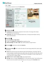
Page 70: ...tection sensor to trigger the event reaction as selected in the Notification Over field below You can set up the tamper duration time in the Event Trigger Settings field below Enable This Event Check the box to activate the event For Alarm Input Manual Trigger and Tampering Detection trigger types multiple events can be created on the Event List but only one event can be enabled For example if you...

Page 71: ...ing will only be as long as the combined Pre and Post trigger Buffers so make sure you enable at least one of these buffers especially the Post trigger Buffer Record to PC Check the box if you want the camera to start recording its video feed when the event occurs on PC Network Alarm Check the box if you want the camera to send a network alarm signal when the event occurs to the CMS servers Note t...

Page 72: ...onfigure the recording schedule here Select the desired recording types among the options below Click and drag the cursor on the time block which will be applied with the selected recording type Event Red Select for the camera to activate all the Event Recording Alarm Input Manual Trigger Motion Detection Tampering Detection Schedule Green Select for the camera to activate normal recording The eve...

Page 73: ...rsor to the position where you want the motion rectangle to start and then click Move the cursor to the position diagonally opposing corner where you want the motion rectangle to end and then click 5 Click the Apply button to apply the settings or click the Cancel button to reset without saving the settings ...

Page 74: ...tings This area is for configuring the mail server that is used to send e mail text notifications and one image file from the camera to predefined addresses via SMTP Note that to enable e mail notification function you have to check the Send Mail Notification box in the Event Management field see 7 3 2 Event ...

Page 75: ...on to send a testing email to the assigned address You will see a Success or a Fail text beside the Test button indicates the test result Click Apply to apply the changes or Cancel to cancel the changes and return to the previous settings FTP Repository Settings This area is for configuring the FTP server that is used to send alarm recordings from the camera to the preconfigured FTP server Note th...

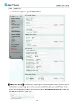
Page 76: ... Make your changes as desired Click on the Trap Address field to enter the digits if required Click Apply to apply the changes or Cancel to cancel the changes and return to the previous settings Network Alarm Settings This function works with EverFocus CMS software The camera can send a network alarm signal when the event occurs to the CMS servers To establish the connection between the camera and...

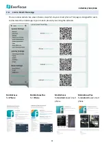
Page 77: ... or take a snapshot via your smart phone This page is designed for users to download the mobile app to your mobile phone by scanning the QR code MobileFocus for iPhone MobileFocusPlus for iPhone MobileFocus for Android based smart phone MobileFocusPlus for Android based smart phone ...

Page 78: ...pears The IPU will automatically search the IP devices connected in the LAN 2 Log in the camera by checking the desired model and then click the Log in icon The Log in dialog box appears 3 Type the Username and Password Click the OK button the Login status displays Note 1 The default user ID is user1 and the default password is 11111111 2 If you select more than one camera that has the same user I...

Page 79: ... 4 Click the Upgrade Firmware button a browsing window appears 5 Select the firmware file evb and then click Open The IPU will automatically upgrade the firmware The camera will reboot once the upgrade process is complete ...

Page 80: ...ution 1920 x 1080 2048 x 1536 1920 x 1080 Frame Rate Dual streams 60fps 1080p 30fps VGA 30fps 30fps Video format 50Hz 60Hz S N Ratio 50 dB Video Streaming Multiple simultaneous streams Image Settings Compression Brightness Sharpness Saturation Auto White balance Exposure control Flicker less Text and image overlay Auto Gain Control AGC Mirroring of images Corridor Format Function Region of interes...

Page 81: ...tection Notification Send mail notification Upload video to FTP Record video to PC and network alarm General Storage Micro SD SDHC card up to class 10 RS 485 RS 485 x 1 Alarm Input Output 1 1 Video Output video test output cable Power Supply 12VDC PoE 24VAC Power over Ethernet IEEE802 3af Class 3 Max Power Consumption IR LEDs on 12 VDC 9 1W PoE 10 2W 24VAC 0 7A 12 VDC 9 1W PoE 10 2W 24VAC 0 7A 12 ...

Page 82: ...op up A When these error messages pop up follow the steps below to fix the problem 1 To enter the Registry Editor of your computer Click Start and type regedit in the Search Program and Files field 2 Click the Enter button the Registry Editor window appears ...

Page 83: ...the KeepAlive Timeout Dword by following the path HKEY_CURRENT_USER Sofware Microsoft Windows CurrentVersion Internet Settings 4 Double click KeepAlive Timeout and this window appears 5 Change the Value data to 480000 and click OK ...

Page 84: ...ssage For Microsoft IE10 and above users you may have the above error message pop up when you click the Snapshot button on the Live View window You can simply solve this problem by setting up your Microsoft Internet Explorer to Run as administrator ...

Page 85: ...u may have the above error message pop up when you click the Snapshot or Record button on the Live View window Follow the steps below to fix the problem 1 To enter the Registry Editor of your computer Click Start and type regedit in the Search Program and Files field 2 Click the Enter button the Registry Editor window appears ...

Page 86: ...out Dword by following the path HKEY_LOCAL_MACHINE SOFTWARE Microsoft Windows CurrentVersion Polic EnableLUA 4 Double click Enable LUA and this window appears 5 Change the Value data to 0 and click OK 6 Restart your computer to complete the setting ...

Page 87: ...have been tested by EverFocus and are recommended to work with EverFocus IP camera Brand Transcend Transcend Kingston SanDisk Team Group SanDisk SanDisk Format SDHC SDHC SDHC SDHC SDXC SDXC SDXC Card Speed UHS I Class 10 UHS I Class 10 UHS I Class 10 UHS I Class 10 UHS I UHS I Class 10 UHS I Class 10 Card Capacity 8GB 32GB 16GB 32GB 64GB 64GB 128GB ...

Page 88: ... function to work the router switch must support multicast function Switch Router Router IP Camera Switch Multicast Streaming To enable the Multicast Function 1 Complete the installation of the IP cameras routers switches and computers refer to diagram above 2 Access to the Web UI of the IP camera to enable the Multicast function Click the Apply button to save the setting Setting Advanced tab Syst...

Page 89: ...60 7360 83 3 Go to the setting page of the router switch to enable the Multicast function Here we use a D Link DIR655 router and EverFocus 24 port switch for example 4 The Multicast function setup is now complete ...

Page 90: ...nnels 0 device ip address is the IP address of the IP camera 0 is for Main Stream 1 is for Sub Stream For example if the IP address of the IP camera is 192 168 37 55 the RTSP URL main stream sub stream of this IP camera will be Main Stream rtsp 192 168 37 55 554 Streaming channels 0 Sub Stream rtsp 192 168 37 55 554 Streaming channels 1 ...

Page 91: ...le the IP camera port forwarding function you have to configure the port forwarding settings both on the IP camera and the router UPnP enabled Please follow the steps below Router Switch IP Camera Notebook Local Network Internet PC 1 Go to Setting System Settings Network a Set up a static IP for the IP camera Type in the subnet mask gateway and the DNS if provided by the Internet Service Provider ...

Page 92: ...up here HTTP 80 HTTPS 443 RTSP 554 2 Set up the port forwarding settings on the router Here we use D Link s router for example Please be noted that each router may look different in some ways however the concept of the port forwarding setting is the same For more details please consult the manual of your router Enter the IP address of the IP camera Enter the HTTP HTTPS RTSP port numbers of the IP ...

Page 93: ...a changes DDNS Dynamic Domain Name System is a service used to map a domain name to the dynamic IP address of a network device It assigns a domain name URL to the IP Camera so that the user does not need to go through the trouble of checking if the IP address assigned by DHCP Server has changed Once the IP is changed the IP Camera will automatically update the information to the DDNS to ensure it ...

Page 94: ...cal network enable either the Port Forwarding or DMZ function of your router Please refer to the manual of your router for more details Note If you enable the Port Forwarding of your router the Enable UPnP Port Forwarding function must be enabled on the IP camera see Port Settings field in the Step 2 image ...

Page 95: ...the IP address subnet mask default gateway and the DNS Server Please consult with your ISP service provider for the information of subnet mask default gateway and the DNS Server If DHCP is selected The IP address subnet mask default gateway and the DNS Server will be assigned automatically by DHCP server If PPPoE is selected Enter the User Name e g xxxx hinet net and Password provided by your ISP ...

Page 96: ... Check Enable Service ISP to enable the DDNS function b Select www everfocusddns com and enter a desired host name in the IP Camera Name field If the host name is available a Success window will appear Click OK If not try another host name until the Success window appears Note The host name should not include a space or a dot period or any special characters particularly _ c Click Apply ...

Page 97: ...ter the domain name http host name everfocusddns com in the address field The Web interface of the device should be displayed For example if you ve obtained the host name HQtest from EverFocus DDNS server enter http HQtest everfocusddns com in the address field of the browser ...

Page 98: ...an 3F Kuramochi Building II 2 2 3 Koto Bashi Sumida Ku Tokyo 130 0022 Japan TEL 81 3 5625 8188 FAX 81 3 5625 8189 www everfocus co jp info everfocus co jp Your EverFocus product is designed and manufactured with high quality materials and components which can be recycled and reused This symbol means that electrical and electronic equipment at their end of life should be disposed of separately from...

Reviews: