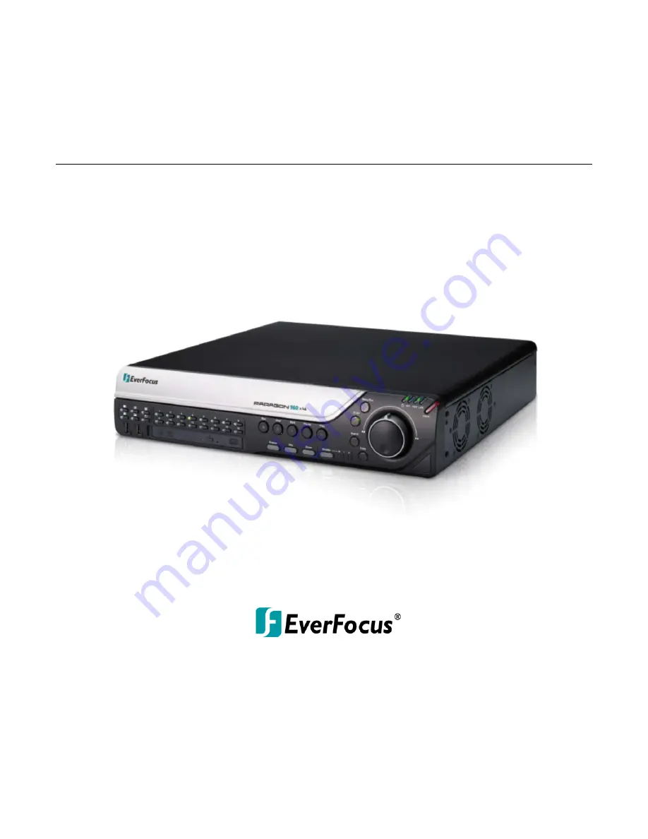
PARAGON960 X4
16CH, H.264, 960H
User’s Manual
Copyright © EverFocus Electronics Corp,
Release Date: June, 2013
Notice: This content is subject to be changed without notice.
Page 1: ...PARAGON960 X4 16CH H 264 960H User s Manual PARAGON960 X4 Copyright EverFocus Electronics Corp Release Date June 2013 Notice This content is subject to be changed without notice...
Page 2: ...e Everfocus Electronics Corporation Release Date June 2013 QuickTime is a registered trademark of the Apple Computer Inc Windows is a registered trademark of the Microsoft Corporation Linksys is a reg...
Page 3: ...d refer servicing to qualified service personnel Moisture may damage the appliance and also may cause electric shock Do not use strong or abrasive detergents when cleaning the appliance body Use a dry...
Page 4: ...ing to qualified service personnel Power Cord Protection Power supply cords should be routed so that they are not likely to be walked on or pinched by items placed upon or against them playing particu...
Page 5: ...connected Consult the dealer or an experienced radio TV technician for help FCC Caution Any changes or modifications not expressly approved by the party responsible for compliance could void the user...
Page 6: ...Checking the Dynamic IP Address 18 2 6 Connecting the DVR to the Network 21 2 5 1 Router or LAN Connection 21 2 5 2 Direct High Speed Connection 24 2 5 3 One to One Connection 25 3 Mouse and Front Pa...
Page 7: ...1 Quick Playback 48 5 2 Playback Bar 49 5 3 Searching the Recordings for Playing Back 51 5 3 1 Time Search 51 5 3 2 Event Search 52 5 3 3 Smart Search 53 5 3 4 Snapshot Search 55 5 3 5 POS Search 57 6...
Page 8: ...6 9 6 Miscellaneous 113 6 10 Information 114 6 10 1 System 114 6 10 2 Log 116 7 Remote Access to the DVR 117 7 1 Accessing the DVR on the Network 117 7 2 Browser Security Setting 118 7 2 1 Installing...
Page 9: ...d VGA monitors with an intuitive onscreen user interface for efficient operation User can also easily operate the machine using a USB mouse or via the front panel buttons and jog dial shuttle wheel Wh...
Page 10: ...Analog Camera 1 16 Power Supply Mouse USB Memory Stick DVD Burner Internal 3 5 HDDs Optional IR Remote Control Network Figure 1 1 Either HDMI or VGA port can be used as the Main monitor output You ca...
Page 11: ...s Supports one eSATA port for external HDD EDA450 Supports live monitoring and playback of video from mobile devices via Mobile applications Multiple Control Inputs Mouse front panel remote controller...
Page 12: ...nformation Please also keep the shipping carton for possible future use 2 Contact the shipper if any items appear to have been damaged in the shipping process 3 Four SATA cables will be supplied for D...
Page 13: ...PARAGON960 X4 5 1 3 Dimensions Front View Side View 423mm 16 65 Figure 1 2...
Page 14: ...k actions and exit the playback area 5 Stop Press to stop either the Reverse Fast Reverse Play and Fast Forward functions if that function is active This button stops all Play functions but no Recordi...
Page 15: ...SB2 0 Ports Two USB2 0 ports for connecting to a mouse or external storage device 14 DVD Burner Optional Use the DVD Burner for archiving the recordings from the DVR It s highly recommended to use a D...
Page 16: ...devices such as speakers Note that the speakers with amplifier are required 6 RS 232 Port This port is currently reserved Connects to the RS 232 device 7 RS 485 Port Connects to the RS 485 device such...
Page 17: ...DDs inside the DVR for recording videos 1 Make sure the DVR is power off 2 Unscrew the two housing screws on the back panel of the DVR Figure 2 1 3 Push the housing to the back and open it Figure 2 2...
Page 18: ...w Figure 2 5 7 Use the SATA Cable and connect one end to the SATA port on the small PCB inside the DVR and the other end to the SATA port on the HDD Figure 2 6 8 Connect the internal power cable to th...
Page 19: ...the HDD tray HDD Tray Figure 2 8 If you need to use four HDDs you have to screw one HDD under the HDD tray a Unscrew eight screws on the HDD tray first and take the tray out HDD Tray Figure 2 9 b Scre...
Page 20: ...racuda SATA3 ST500DM002 500GB Barracuda SATA3 ST1000DM003 1TB Western Digital WD10EVDS SATA2 1TB WD10EURS SATA2 1TB WD20EVDS SATA2 2TB WD20EURS SATA2 2TB WD30EURS SATA3 3TB WD1600AVVS SATA 160GB WD320...
Page 21: ...Using the supplied Power Cord connect one end to the 100 240 VAC port on the DVR and the other end to the 100 240 VAC power outlet Note Please ensure to connect the internal power cables to the inter...
Page 22: ...1080 progressive 60 Hz Vert 68 KHz hor so if you select VGA output device resolution selected should be supported by the monitor Resolution selected higher than the monitor can support may cause the...
Page 23: ...to also change the camera live view display to 16 9 aspect ratio in the Ratio drop down list see 6 2 1 Basic Setting Screen Mode 1920x1080 16 9 Camera Ratio 16 9 Camera Ratio 4 3 Figure 2 14 If selec...
Page 24: ...ND Alarm Input Contacts This DVR provides one alarm input per camera All inputs are programmable N O Normal Open or N C Normal Closed All settings are programmed in the ALARM Event menu ALMIN GND ALMI...
Page 25: ...0 X4 is a 9 pin D Sub socket For details on the RS 232 configurations on the DVR please refer to 6 9 5 I O Control PARAGON960 X4 Figure 2 18 2 4 Turning On Off the Power Before powering on the DVR ple...
Page 26: ...e DVR in the same LAN of your computer 1 Install and then start the IPU program The following dialog box appears Figure 2 19 2 IPU will automatically search the IP devices connected in the LAN The def...
Page 27: ...if you are unsure of your network settings please consult your network administrators for configuration details 6 To access the DVR highlight the DVR and click Connect to Selected IP The Internet Exp...
Page 28: ...e Remote Live View 11 On the computer click Start Control Panel System and Security Action Center click Change User Account Control Settings the User Account Control Settings window appears Adjust the...
Page 29: ...to a router and allows multiple users on and off site to see the DVR on a LAN WAN Internet The DVR must be assigned an IP address that is compatible with its LAN By setting up port forwarding on the r...
Page 30: ...nu To let the router automatically assign an address Set the Network Type to DHCP Make sure to write down the IP address and the Gateway Exit from the Menu to save settings To manually assign an addre...
Page 31: ...your router Log into the router using a PC and open the following ports Ports to open 80 If your Internet service provider blocks port 80 you can change it to a different port in the DVR s Network Men...
Page 32: ...a cross over network cable for this application Once you have a straight through cable plug one end into the LAN port on the back of the recorder and the other into the high speed modem Log into the E...
Page 33: ...lease remember you can not use a straight through network cable for this application Once you have a cross over cable plug one end into the LAN port on the back of the DVR and the other into the netwo...
Page 34: ...PARAGON960 X4 26 Go to Start Double click on Control Panel Figure 2 28 Click Network and Internet Connection Figure 2 29 Click Network Connections Figure 2 30...
Page 35: ...k Properties Figure 2 32 Select Use the following IP address Assign an IP address of 192 168 1 2 a Subnet Mask of 255 255 255 0 and a Default Gateway of 192 168 1 1 and then click OK Restart both of t...
Page 36: ...gn an IP address of 192 168 1 2 a Subnet Mask of 255 255 255 0 and a Default Gateway of 192 168 1 1 and then click OK Restart both of the computer and the DVR To access the DVR from the computer simpl...
Page 37: ...t a Channel Enable Audio 1 In the Live View window you can select a channel by clicking once on the desired channel screen The selected screen will be highlighted by a red frame 2 Double clicking on a...
Page 38: ...The buttons on the right and bottom have the following functions Drop Down Box Click on the down arrow to see all selections then directly click on an option to select it Check Box Click on the box to...
Page 39: ...g the Jog Shuttle wheel clockwise or counterclockwise The selected channel will be highlighted with a red frame 2 After selecting a channel press the Enter button to turn On Off the Audio function An...
Page 40: ...oard and then press the Enter button to confirm Caps Switch to capital letters Delete the letter backwards Confirm the selection Move to left Move to right Space Enter a space Drop Down Box Press the...
Page 41: ...Shuttle on the front panel the Login window appears Figure 3 3 2 The default user name and password are User admin Password 11111111 Note For details on setting up multiple user accounts please refer...
Page 42: ...lect a camera follow the instructions below Using a mouse Click a camera on the screen and the selected camera will be highlighted with a red frame All cameras will be selected when you scrolling the...
Page 43: ...ired camera by Using a mouse On the bottom of the screen click the Audio icon to switch the Audio Output function to the desired camera or disable the Audio Output function Using the front panel butto...
Page 44: ...videos For details please refer to 5 Search and Playback 2 PTZ Click to display the PTZ Control Panel for controlling the connected PTZ cameras For details please refer to 4 1 PTZ 3 Layout Click to di...
Page 45: ...ching 8 Zoom Click to enter the Zoom mode You can zoom in the camera view up to x4 and navigate the camera view For details please refer to 4 7 Zoom 9 Search Click to display the Search menu for setti...
Page 46: ...Iris buttons 5 To program a Preset Position if supported by the camera a Move the PTZ camera to the desired position b Click the Preset button c Set up a preset number for the current position by clic...
Page 47: ...y the camera a Click the Tour button b Click the desired Tour number c Click the Delete button Click C to clear the entered number in the Number Box Click at the top right corner to hide the PTZ Contr...
Page 48: ...nd zoom by clicking directly on the screen Figure 4 3 Direction Controls When your mouse cursor turns into a direction icon click on the screen will force the camera to turn in that direction Focus Co...
Page 49: ...desired Screen Layout button on the front panel of the DVR To display a channel in full screen press the channel buttons on the front panel 4 3 Channel Switching You can switch the selected camera to...
Page 50: ...mera s status Recording Playback Fast forward Fast backward Back pause Alarm Motion Video loss Uninstall Audio On 3 The following icons will be displayed at the bottom of the monitor to show the syste...
Page 51: ...will be displayed in the sequence and for the amount of time as configured in the System Display Setting M T SEQ submenu Please refer to 6 6 2 M T SEQ for detailed information 4 6 Monitor Switching Y...
Page 52: ...ayed on the top screen 2 Navigate the camera view to the desired position by moving your mouse cursor over the camera view The mouse cursor will turn into a direction icon when you move your mouse cur...
Page 53: ...in stream sub stream or Meta If you want to archive the recordings with the POS transaction data select the Meta in the drop down list Player Check the box to include the EFPlayer program in the copy...
Page 54: ...as Figure 4 9 Press Yes when you are ready to logout of the system You will need to login again before accessing the OSD Root Menu Figure 4 9 If you do not need the Login Logout step before entering t...
Page 55: ...able the Temporarily Logout function follow the steps below Ensure the User Login box is Unchecked Figure 4 10 1 Select the cameras to be hidden once enabling the Temporarily Logout function and then...
Page 56: ...back box in the Express setting page OSD Root Menu System Express to enable the configured time in the field below 2 Enter the desired time for playing back the recording Take 60 seconds for example i...
Page 57: ...vent 3 Playback Speed Indicates the current Playback Speed 4 Express Copy Click to bring up the Copy menu for archiving the recordings log data to the USB storage device or DVD burner For details plea...
Page 58: ...ays L2 Entire Time Bar scale is 2 weeks L3 Entire Time Bar scale is 1 week L4 Entire Time Bar scale is 1 day L5 Entire Time Bar scale is 1 hour L6 entire Time Bar scale is 30 minutes 13 Time Bar Scale...
Page 59: ...apshot Search or POS search to enter to the setup menu To bring up the Search menu By Mouse Right click to bring up the OSD Root Menu and then click the Search button By Front Panel Press the Search b...
Page 60: ...to bring up the on screen clock to select the start end time Camera Select the desired cameras to be searched Event Select an event type to be searched Search Click to start searching The search resu...
Page 61: ...ng Click to set up the motion areas The Motion Grid Setup menu appears Search Click to start searching The search results will be listed in the Event List menu see Figure 5 6 To set up the Motion Grid...
Page 62: ...ck to select the entire area Clear All Click to clear all the selected areas Save and Back Click to save the configured motion areas and return to the Smart Search menu Cancel Click to cancel all chan...
Page 63: ...creen clock to select time Search Direction Click to search forward backward based on the setup time above Search Camera Select a desired camera to be searched Result Interval Click to set up the inte...
Page 64: ...2 Right click on the screen the Resume Playback Bar appears in the middle of the screen Previous Play Close Next Figure 5 11 3 Click the Previous or Next buttons to display the previous next snapshot...
Page 65: ...select the start end date Start Time End Time Click to bring up the on screen clock to select the start end time POS String Click to bring up the on screen keyboard Type any desired keyword to search...
Page 66: ...the POS system Select the Text Insert in the Type drop down list OSD Root Menu System System Setting I O control Figure 5 14 3 Check the Text Insert box in the Monitor OSD setting page to display the...
Page 67: ...or the optional device EKB500 keyboard The following operations are examples of using a Mouse This chapter describes the functions and options of the Configuration Setting in the on screen display OS...
Page 68: ...5 Hard Disk 6 5 1 Disk 6 5 2 Lock Format 6 5 3 RAID 6 6 Display Setting 6 6 1 Monitor OSD 6 6 2 M T SEQ 6 7 Network 6 7 1 LAN 6 7 2 Email 6 7 3 DDNS 6 7 4 FTP 6 7 5 Alarm Server 6 7 6 Remote Mobile 6...
Page 69: ...gs without any changes Please refer to 6 8 1 Express Setup for more details Normal Event Set all cameras to the Continuous and Event recording mode Set up the estimated number of hours per day for eve...
Page 70: ...0 30 or 60 minutes For example if you set up 60 minutes for the Archive Interval the DVR will archive the recordings 60 minutes ago from the current time to the storage device on the DVR 3 Press and h...
Page 71: ...e supports up to 16 characters Install Check the box to enable the selected camera Covert Check the box to hide the camera stream in Live View and Sequence modes However the DVR will still record the...
Page 72: ...PAL per individual camera respectively real time recording Event Speed Select a frame rate per second FPS for event recording Ratio Select 4 3 or 16 9 display aspect ratio of a camera and its video wi...
Page 73: ...selected camera Figure 6 4 Camera Select a camera to adjust the following settings Brightness Move the bar to adjust the brightness Contrast Move the bar to adjust the contrast Color Move the bar to...
Page 74: ...ate and time on the bottom top of the image Select off will not record the system date and time in the recordings Record Status Relay Output Select a number to monitor the recording status of the sele...
Page 75: ...rs Note that the pre alarm recording rate will follow the Normal Speed configured in the earlier section see 6 2 1 Basic Setting Buzzer Check the box to enable the buzzer when an alarm event is trigge...
Page 76: ...nds Timeout Duration This function only appears when you select Timeout or Trans Timeout options in the Output Type drop down list Select a duration time for the motion event The alarm output will las...
Page 77: ...Normal Speed configured in the above section see 6 2 1 Basic Setting Buzzer Check the box to enable the buzzer when a video loss event is triggered Email Notify Check the box to send email notificatio...
Page 78: ...ets the alarm remotely Transparent Alarm output remains as long as the alarm input is active Trans Timeout Alarm output continues until event ends then continues for the setup duration time 10 150 sec...
Page 79: ...tion see 6 2 1 Basic Setting Buzzer Check the box to enable the buzzer when a motion event is triggered Email Notify Check the box to send email notification when a motion event is detected Email oper...
Page 80: ...is active Trans Timeout Alarm output continues until event ends then continues for the setup duration time 10 150 seconds Timeout Duration This function only appears when you select Timeout or Trans T...
Page 81: ...w Step 3 to set up multiple motion areas if necessary 6 Sets up the Sensitivity Min Area and Motion Delay for the motion grids Sensitivity Sets up the motion sensitivity for the grids The larger the n...
Page 82: ...alarm event is detected Email operation requires valid email entered in the Email setup menu see 6 7 2 Email Network Alarm Check the box to send out a network alarm to a client PC when an alarm event...
Page 83: ...a client PC This feature works with EverFocus CMS software You will need to configure the Alarm Server for the DVR to send network alarms to the client PC see 6 7 5 Alarm Server Stop Recording Check...
Page 84: ...twork Alarm Check the box to send out a network alarm to a client PC when HD fails This feature works with EverFocus CMS software You will need to configure the Alarm Server for the DVR to send networ...
Page 85: ...an alarm is triggered the signal will be transmitted through the selected alarm output relay Output Type Select an output type when HD is full Timeout Select this option and then set up the Timeout Du...
Page 86: ...transmitted through the selected alarm output relay Output Type Select an output type when HD is off Timeout Select this option and then set up the Timeout Duration in the field below the alarm output...
Page 87: ...menu see 6 7 2 Email Network Alarm Check the box to send out a network alarm to a client PC when power has been restored This feature works with EverFocus CMS software You will need to configure the...
Page 88: ...ll remain active until the user presses the Enter key on the IR Remote Control or resets the alarm remotely Transparent Alarm output remains as long as the alarm input is active Trans Timeout Alarm ou...
Page 89: ...Start Shows the earliest recording time of the DVR Record Time End Shows the latest or most current time on the DVR Disk Select a disk number Health Status Displays the current status of the selected...
Page 90: ...Alarm Current Lock Displays the current percentage of the locked event recordings in the hard disk If the amount of locked event recordings has reached the maximum lock percentage the DVR will be una...
Page 91: ...D RAID 0 RAID 0 is designed to improve disk speed Data is written to two disks alternatively instead of just one which improves the overall system speed Note that if the two HDDs are with different ca...
Page 92: ...disabled To enable RAID 0 1 follow the steps below 1 Select RAID 0 or RAID 1 the following message appears Click Yes to configure the RAID settings And the DVR will automatically reboot Figure 6 20 2...
Page 93: ...ck the box to display playback date time only for main monitor Playback Status Check the box to display playback status only for main monitor Text Insert Check the box to display text inserted Screen...
Page 94: ...itor The Sequence will repeat continuously from step 1 to step 20 until interrupted Figure 6 22 Monitor Select Main or Call Monitor to configure the sequencing order Step The sequencing order Camera S...
Page 95: ...PoE to configure an IP address to the DVR Figure 6 23 LAN Port Select LAN1 or LAN2 from the drop down list Install Check the box to enable the network connection Network Type Three options are selecta...
Page 96: ...e network settings if you set up your DVR in this manner its IP address may change at different times for different reasons particularly after a power failure If the IP address of the DVR changes you...
Page 97: ...the average site If you only plan to view your DVR on a LAN you can use port 80 and don t have to concern yourself with DDNS or routers However if you desire remote access to your DVR perhaps using DD...
Page 98: ...cation to be encrypted by SSL User Name Input the login user name if the SMTP server requires authentication Password Input the password if the SMTP server requires authentication Confirm Input the pa...
Page 99: ...ble of checking if the IP address assigned by DHCP Server has changed Once the IP is changed the DVR will automatically update the information to the DDNS to ensure it is always available for remote a...
Page 100: ...ut the desired name for the DVR Note that the name of the DVR cannot include a space or a dot period or any special characters particularly Note 1 It is not necessary to append the HTTP port number to...
Page 101: ...from the DDNS Service drop down list 4 Enter the host name in the Host Name field Note that the name of the DVR cannot include a space or a dot period or any special characters particularly _ 5 Enter...
Page 102: ...or snapshots please see 6 4 1 Alarm and 6 4 3 Motion Figure 6 28 FTP Server Enter the IP address or the host name of the FTP server Port Enter the port number for the FTP server Default is 21 User Na...
Page 103: ...ed to up to 3 addresses Protocol Select the protocol type for alarm transmission Note the protocol selected here should match the protocol set up for the CMS alarm server UDP User Datagram Protocol TC...
Page 104: ...se the FTP function for uploading the recordings MP4 video format please select the H 264 codec Figure 6 30 H 264 The H 264 codec is compatible with iOS and Android MobileFocus applications and IE Web...
Page 105: ...problems by obtaining responses from nodes progressively farther along the network DNS functionality can also be confirmed by entering a valid DNS name instead of an IP address Figure 6 31 To verify...
Page 106: ...time End Select a weekday end time Nighttime schedule ends when Daytime ends Record Type Select a recording type for each time period Disable No recording during the scheduled time period Normal Event...
Page 107: ...he selected group above Disabled Select to disable the Holiday Others recording schedule One time Select this option and then set up the specific date and year in the Details field The DVR will start...
Page 108: ...ock for Holiday Hol Other Oth Sunday Sun Monday Mon Tuesday Tue Wednesday Wed Thursday Thu Friday Fri or Saturday Sat Time 0 23 The numbers represent the 24 hours of a day Time Bar The time bar uses t...
Page 109: ...on Every time the user clicks the first block of a section the color switches from gray pink blue green 4 Repeat the above steps to configure the record modes You can configure up to six record modes...
Page 110: ...turn into gray which means this gray timezone has been set to the recording mode of gray No Rec User can also change the timezone to a different record mode with different color by following the inst...
Page 111: ...peed is limited by the maximum total recording capacity of the DVR as allocated across TV standard in global setting all the installed cameras with an upper limit of 30 FPS NTSC 25 PAL per individual...
Page 112: ...ar All deselects all days Click OK to copy the settings or Cancel to exit without copying Figure 6 41 Apply to Cameras This button can be used to copy schedules to other cameras Select which cameras y...
Page 113: ...e DVR to adjust to when updating from the time server NTP Select Disable Enable for NTP time synchronization NTP Server Displays the time server address that the DVR uses for time synchronization Requ...
Page 114: ...mm Set the time when daylight saving time begins Set To hh mm This is what the time will change to when daylight saving begins For most regions this will be one hour ahead of the Start Time End Date...
Page 115: ...e User Management setting page see 6 9 4 User Management For example if this box under the Operator level has been checked any user with the Operator privilege can go to the User Management setting pa...
Page 116: ...unt to a new user account Edit Click the button to edit the settings of an existing user account Add Click the button to add a new user Delete Click the button to delete Login Check the box to enable...
Page 117: ...he keyboard and input the desired user name User Group Select a user group access level Status Select to enable or disable the user account Password Input the password Confirm Enter the same password...
Page 118: ...PARAGON960 X4 110 Figure 6 48...
Page 119: ...ation through the RS 232 port on the DVR There are eight different speeds 1200 BPS 2400 BPS 4800 BPS 9600 BPS 19200 BPS 38400 BPS 57600 BPS and 115200 BPS Data Bit This field is the data bit at which...
Page 120: ...s 1200 BPS 2400 BPS 4800 BPS 9600 BPS 19200 BPS 38400 BPS 57600 BPS and 115200 BPS Data Bit This field is the data bit at which you will be transferring There are two settings for this option 8 or 7 S...
Page 121: ...ll need to restore the firmware file to the USB flash device and then connect the USB flash device to the DVR Configurations Load Factory Default Click to restore the DVR to factory default settings T...
Page 122: ...Version Displays the firmware version Model Displays the model name of the DVR NTSC PAL Displays the current video format automatically detected by the DVR S N Display the serial number of the DVR La...
Page 123: ...al hard disks Normal hard disk operation is indicated by OK Disk 5 8 Displays the status of the external eSATA storage device Normal eSATA storage device operation is indicated by OK Fans Displays the...
Page 124: ...set up the start end date Start Time End Time Click to bring up the on screen clock to set up the start end time Log Type Select the desired log types View Log Click to bring up the Log List shown as...
Page 125: ...al connection http IP address from the DVR s Network Menu IP port used e g http 192 168 1 163 2468 Internet connection http IP address given by your Internet Service Provider IP port used e g http 57...
Page 126: ...install the JAVA software or its latest version on your computer Figure 7 2 2 Please click OK to go to the JAVA website http www java com en and download the latest version of the JAVA software 3 Afte...
Page 127: ...nd select Run Add on Figure 7 4 6 Install the MSXML file when prompted to do so Figure 7 5 7 Now you will be able to see the remote live page Figure 7 6 8 Please refer to 2 5 Checking the Dynamic IP A...
Page 128: ...ary if you DO NOT see the dialog Figure 7 2 popping up when you first connect to the DVR 1 At the top of the Internet Explorer Window click on Tools and then select Internet Options Figure 7 7 2 Click...
Page 129: ...ly Automatic prompting for ActiveX controls Binary and script behaviors Display video and animation on a webpage that does not use external media player IE7 only Run ActiveX controls and plug ins Scri...
Page 130: ...age Figure 7 10 7 Install the EverfocusViewer file when prompted to do so Figure 7 11 8 Once the file finishes installing you will return to the same login page as before Type in the user name and pas...
Page 131: ...ker button to transfer audio to the client side from DVR if there is a speaker on the PC and a microphone and preamp attached to the DVR and audio recording is enabled on the DVR Click the Microphone...
Page 132: ...m White Indicates the live view is in a normal status Orange Indicates a motion is being detected Blue Indicates video loss Red Indicates an alarm event is triggered Grey Indicates the live view is di...
Page 133: ...r displaying the camera information on the camera live view Please refer to 6 6 Display Settings 8 Network Click to configure the network settings Please refer to 6 7 Network Settings 9 Schedule Click...
Page 134: ...Search Event Search or Smart Search and then set up the settings For more details about Search setting please refer to 5 3 Searching the Recordings for Playing Back Double click on a recording the fol...
Page 135: ...PAL auto detected by system Video Inputs 16 x BNC Video Outputs Main HDMI or VGA selectable Call BNC HDMI or VGA selectable Looping Outputs 16 x BNC Recording Recording Frame Rate NTSC 30 fps ch at W...
Page 136: ...13 2 lbs without HDDs Language English Japanese Traditional Chinese Spanish Deutsch French Russian Portuguese Brazil Dutch Simplified Chinese Regulatory CE FCC UL Applications Remote View Support Remo...
Page 137: ...n Verify the recorder is getting the correct supply power There is no display coming from one of the channels on the DVR In the DVR s Camera Menu make sure that all cameras are checked as Installed an...
Page 138: ...the LAN For example one computer on a network could have an IP address of 192 168 1 127 You should never give two or more devices the same exact IP address but the first three octets of an IP address...
Page 139: ...t the lower end of the range such as 80 for HTTP Ports are similar to doors and windows of your house with port 80 acting as the front door If these are not open you could not enter the house This is...
Page 140: ...c IP address ______________ A Static IP address means you use the same IP address every time you connect to the Internet With a static IP address other Internet users always know the address of your l...
Page 141: ...ect connection from one computer to another or in this case a computer to a DVR Direct High Speed Modem Connection A direct modem connection uses a standard network cable to connect the modem directly...
Page 142: ...s the Web based Utility launch a web browser and type the Router s IP address typically 192 168 1 1 in the address bar Then press Enter A password request page will appear Non Windows XP users will se...
Page 143: ...mber of the range under Start and the ending number under End Protocol Enter the protocol used for this application either TCP or UDP or Both IP Address For each application enter the IP Address of th...
Page 144: ...it If you need additional technical support on this router you must call D Link Whenever you want to configure your network or the DI 624 you can access the Configuration Menu by opening a web browse...
Page 145: ...e port number that the service uses on the LAN Local Area Network Public Port The port number that the services uses on the WAN Wide Area Network Schedule The time period the virtual server will be ac...
Page 146: ...alarm mode related to event record alarm outputs OSD message buzzer Timeout Transparent Mode t Input Event Alarm Duration t Duration t Reaction t Event t Event Duration of alarm input source motion c...
Page 147: ...tion Resulting duration for this alarm mode related to event record alarm outputs OSD message buzzer Permanent Mode t Input Event Alarm Duration t Reaction t Event Alarm Reset t Event Duration of alar...
Page 148: ...action Resulting duration for this alarm mode related to event record alarm outputs OSD message buzzer Timeout Transparent Mode Retrigger of Alarms t Event Duration of alarm input source motion contac...
Page 149: ...set 8 Checking Order 1 2 3 4 5 6 7 8 Normal Frame Rate 1 1 1 1 1 1 1 1 Quality Superior Standard Low Low Low Low Low Low Event Frame Rate 30 30 30 15 10 7 5 5 1 Case 2 Record Mode Event Only Record W...
Page 150: ...rding to the Preset Settings Preset Setting Option Camera Item Apply value Best Quality Quality Superior Normal Frame Rate Max recording frame rate of DVR Event Frame Rate 30 Standard Quality Quality...
Page 151: ...e remote control The effective distance is up to 33 feet line of sight ID number here must correspond to the IR Remote ID set up in the I O Control Menu Channel keys 1 16 The buttons are used to selec...
Page 152: ...ww everfocus co jp info everfocus co jp EverFocus Europe UK Unit 12 Spitfire Business Park Hawker Road Croydon Surrey CR0 4WD UK TEL 44 20 8649 9757 44 845 430 9999 FAX 44 20 8649 9907 www everfocusuk...