background image


21 


3.3.3.4 BLC-Backlight Compensation. There are three choices for the type of BLC which may be 

employed: OFF, traditonal BLC or HSBLC.  

BLC 

Video gain can be adjusted automatically to correct the exposure of subjects that are in front of a 
bright light source.  
Please direct the arrow to point to “BLC” by using the UP and DOWN buttons.  
Select the BLC mode by pressing the LEFT or RIGHT button. Then make adjustments as below: 
 

GAIN 

 Select from High, Middle and Low.  


DEFAULT 

 Set the factory default values for BLC.  


LEFT/RIGHT 

 Set the Left/Right side of an area for the BLC to be adjusted. The value 
adjustable is 0~6. 


WIDTH 

 Set the width of an area for the BLC to be adjusted. The value adjustable is 
0~6. 


TOP/BOTTOM 

 Set the Top/Bottom side of an area for the BLC to be adjusted. The value 
adjustable is 0~6. 


HEIGHT 

 Set the height of an area for the BLC to be adjusted. The value adjustable is 

0~6. 


RETURN 


Press “RET” to save all settings in the BLC menu and return to the previous 

menu.  
Press “END” to save all the menu settings and exit. 


HSBLC 

HSBLC (Highlight Suppression BLC) is used to reduce the brightness of light sources in a 
specific area. It is activated only in a low illumination environment to minimize the effects of glare 
from bright lights such as spotlights, street lights or headlights in the field of view. Where 
‘traditional’ BLC can increase the exposure of a dark area surrounded by a brighter area, HSBLC 

can decrease the exposure of bright areas surrounded by darker areas.  
 

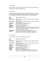
1. Please direct the arrow to point to “BLC” by using the UP and DOWN buttons.  
2. Select the HSBLC mode by pressing the LEFT or RIGHT button. Then make adjustments as 

below: 

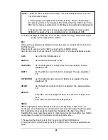
NOTE: 

1. SENS-UP will be disabled, if AGC is OFF or the default SHUTTER value (1/50 PAL / 

1/60 NTSC) was changed


2. The image becomes brighter when the setting increases; however, the after image 
increases as well. Due to the increased light sensitivity of the Super HAD II chip, far less 

DSP ‘boost’ is needed, resulting in color or B/W images in low light with minimal ghosting. 


3. Please note that spots and noise may appear if light amplification increases when 
SENSE-UP is operating. This is a normal phenomenon, controllable with DNR. 

Summary of Contents for EZ610

Page 1: ...Installation Operation Instructions E EZ Z6 61 10 0 L Lo ow w L Li ig gh ht t I In nl li in ne e I IP P6 66 6 B Bu ul ll le et t C Ca am me er ra a EverFocus ...

Page 2: ...hould be retained for future reference The information in this manual was current when published The manufacturer reserves the right to revise and improve its products All specifications are therefore subject to change without notice All rights reserved No part of the contents of this manual may be reproduced or transmitted in any form or by any means without written permission of the EverFocus El...

Page 3: ...and other liquids and never touch the power cord with wet hands Touching a wet power cord with hands or touching the power cord with wet hands may result in electric shock 5 Never install the camera in areas exposed to oil gas or solvents Oil gas or solvents may result in equipment failure electric shock or in extreme cases fire 6 Cleaning Do not touch the surface of the sensor directly with the h...

Page 4: ...ed by the party responsible for compliance could void the user s authority to operate this equipment This device complies with Part 15 of the FCC Rules Operation is subject to the following two conditions 1 This device may not cause harmful interference and 2 this device must accept any interference received including interference that may cause undesired operation This Product is RoHS compliant A...

Page 5: ...RE 20 3 3 3 1 SHUTTER 20 3 3 3 2 AGC Auto Gain Control basic low light signal amplification 20 3 3 3 3 SENS UP 20 3 3 3 4 BLC HSBLC Error Bookmark not defined 3 3 3 5 D WDR 22 3 3 4 WHITE BALANCE CONTROL 22 3 3 5 DAY NIGHT 23 3 3 6 3DNR 24 3 3 7 SPECIAL 25 3 3 7 1 CAM TITLE 25 3 3 7 2 D EFFECT 26 3 3 7 3 FREEZE 26 3 3 7 4 MIRROR 26 3 3 7 5 D ZOOM 26 3 3 7 6 GAMMA 26 3 3 7 7 NEG IMAGE 26 3 3 7 8 RE...

Page 6: ...e control with EKB 500 keyboard 30 4 1 1 RS 485 Wiring 30 4 1 2 OSD Menu Setting by Keyboard 30 4 1 3 Lens Adjustment by Keyboard 31 4 2 Remote Control with EverFocus DVR 31 4 2 1 RS 485 Wiring 31 4 2 2 Camera Operation and Setup by DVR 31 ...

Page 7: ...6X sens up to a max of 0002 lux and much more this is the camera you have been waiting for and might be the only camera you ll ever need 1 1 Features Super HAD II sensor at 0 05 lux has 5X better native light sensitivity before DSP low light boost Color without compromise your choice of full motion color or true day night images in low light without ghosting True Day Night with ICR module field se...

Page 8: ... attaching EZ Mount Ring to mounting surface Short Screws x 4 for connecting camera base to EZ Mount Ring Expanding Anchors x 4 Hex key x 1 for adjusting camera Hexagon wrench x 1 for adjusting sunshield and set screw in base Mounting Template x 1 Note If an item appears to have been damaged in shipment replace it properly in its carton and notify the shipper If any items are missing notify your E...

Page 9: ...le functions 3D DNR Off On switchable Digital WDR Off Outdoor Indoor Digital Slow Shutter Sens Up up to 256X Mirror Off Mirror V Flip Rotate Selectable Digital Zoom Off On selectable up to 32X Motion Detection Off On for 4 selectable zones Privacy Mask Off On for 8 selectable zones RS 485 2 wire simplex address 1 99 1200 9600 baud EverFocus or Pelco D protocol self detecting Power Source 12VDC 24V...

Page 10: ...10 1 4 Dimensions Camera Base Camera Body Front view of EZ610 ...

Page 11: ...adjust focus 3 Lens Menu Lens LED will turn green when you select the Lens adjustment mode Menu LED will turn red when you select the Menu setting mode 4 Video GND for aim and focus access to video at the camera use the Video Test Cable supplied to connect to a hand held test monitor EN220 or similar 1 6 RelatedProducts In addition you may order the following EverFocus products which are recommend...

Page 12: ...ll be used please insert the provided plug into the ring from the underside the plug will be held securely in place by the ring If surface wire access is required simply omit the plug to leave the surface wire channel clear Push the plastic anchors into the 4 holes 3 Take a long Phillips pan head screw and tighten it through the EZ Mount Ring counter bored hole into a plastic anchor Repeat this st...

Page 13: ...Connect the power and video cables Attach the camera to the speedy mount ring securing it with the 4 screws provided Power and Video connection Note For details of RS 485 connection please consult chapter 4 for Rs 485 setup chapter 3 2 White RS 485 Black RS 485 Optional ...

Page 14: ...nique 3 axis positioning system installers can capture images from virtually any angle without compromising The camera can be adjusted in 3 ways 1st axis 2nd axis Use a hexagon key to loosen this screw to rotate the camera 360 Use a hexagon key to loosen this screw to rotate the camera 180 ...

Page 15: ... sunshield Note When properly installed the rear of the sunshield is even with the rear of the camera body improperly extending the sunshield to shade the lens can compromise image quality Loosen lock ring and set screw to rotate camera 360 Slide rib on interior of sunshield into track on outside of camera body from front to back ...

Page 16: ...ini joystick to bring up the general OSD menu Note Make sure that the joystick is in MENU mode red LED under Joystick Navigate among the OSD Menu Items Turn the mini joystick up c or down d to move the cursor up or down Change Modes or Setting Parameters Turn the mini joystick left e or right f to adjust the mode or value of settings Switch to Sub menu Screens When an item with a sub menu is selec...

Page 17: ... for 3 seconds The camera will perform a factory reset after this the current RS 485 address is shown on the top of the screen Example ID 01 RS485 ID is adjustable in the range 01 99 Default value is 01 Move joystick UP and Down to adjust it Press Set key to confirm the setting Now the current Baud Rate appears on the top of the screen Example 9600 The Baud Rate is adjustable for the values 9600 4...

Page 18: ... OFF BLC OFF BLC Gain Low Middle High Default Left Right Width Top Bottom Height Return HSBLC Level 0 8 5 Default Left Right Width Top Bottom Height Return D WDR Off Indoor Outdoor Return White Balance ATW AWB AWC SET Manual Red 0 100 25 Blue 0 100 35 Return Indoor Outdoor Return Day Night EXT Auto Delay 0 63 5 S Level 0 100 56 D Level 0 100 6 Color Black White Burst Off On Return Return 3DNR ON L...

Page 19: ...0 93 Top Bottom 1 60 Height 0 60 Sensitivity 0 40 Motion View Off On Return Privacy Off On Area Select Area1 Area4 Area Display Off On Left Right 6 98 Width 0 93 Top Bottom 0 60 Height 0 61 Color 0 15 Return Sync INT LL Language English Trad Chinese Simp Chinese Japanese Return Return Adjust Sharpness 0 31 16 Blue 0 100 63 Red 0 100 63 Reset Factory Return Exit ...

Page 20: ...s the SETUP button when you finish all the settings 3 3 3 2 AGC Auto Gain Control basic low light signal amplification Please direct the arrow to point to AGC by using the UP and DOWN buttons Select the level you would like to choose by pressing the LEFT or RIGHT button The more the level of gain increases the brighter the screen but the level of noise increases as well Please select from HIGH MID...

Page 21: ...o save all the menu settings and exit HSBLC HSBLC Highlight Suppression BLC is used to reduce the brightness of light sources in a specific area It is activated only in a low illumination environment to minimize the effects of glare from bright lights such as spotlights street lights or headlights in the field of view Where traditional BLC can increase the exposure of a dark area surrounded by a b...

Page 22: ... both bright and dark areas at same time this function can help make both areas more evenly exposed 1 Please direct the arrow to point to D WDR by using the UP and DOWN buttons 2 Select the mode you would like to operate by moving the joystick LEFT or RIGHT OFF Disables D WDR function default INDOOR Select this option if you are in an indoor environment OUTDOOR Select this option if you are in an ...

Page 23: ...RET to saves all settings in this menu and returns to the previous menu Press END to save all the menu settings and exit 3 3 5 DAY NIGHT These settings control the operation of the camera when the illumination level changes Choices are Color at all times B W at all times or color when illumination is bright switching to B W in low light EZ610 camera will have excellent IR sensitivity when displayi...

Page 24: ...d Night mode EXT The picture will switch automatically to color in a normal environment and to B W when the ambient illumination is low based on the illumination reaching the light sensor at the front of the camera body 3 3 6 3DNR 3DNR reduces the background noise in a low luminance environment OFF Disables 3DNR to keep the same amount of noise ON Enables 3DNR to reduce the noise default Level Noi...

Page 25: ... RIGHT button Press SETUP button Maximum 15 characters can be used for the ID Use UP DOWN LEFT and RIGHT buttons to move the cursor to the letter to be chosen Use SETUP button to choose that letter Once a name has been selected please choose a position where you would like to display the name Move the cursor onto POS and press the SETUP button The name will appear at the top left hand corner Pleas...

Page 26: ...fied image in view 0 is the center of the image Pan Select digital pan from 100 to 100 Tilt Select digital tilt from 100 to 100 Press RET to saves all settings in D ZOOM menu and returns to the previous menu Press END to save all the setting menus and exit 3 3 7 6 GAMMA This menu allows adjustment of gamma correction for ideal linearity of image brightness and contrast in the range 0 05 to 1 0 3 3...

Page 27: ...sitivity level for the motion trigger by selecting from 0 40 When the sensitivity value is high motion detection sensitivity increases to sense very small movements and vice versa MOTION VIEW Select ON to display motion detection pixels in the live view RETURN Press RET to save all settings in MOTION menu and return to the previous menu Press END to save all the menu settings and exit 3 3 7 10 PRI...

Page 28: ...Press RET to save all settings in the SPECIAL menu and return to the previous menu Press END to save all the menu settings and exit 3 3 8 ADJUST Adjust sharpness Blue and Red level in this section 3 3 8 1 SHARPNESS The contour of the video image becomes cleaner and more easily distinguished as the level of SHARPNESS increases If the level is set too high it may affect the video image and cause noi...

Page 29: ...set to the default settings Press RET to return to the previous menu Press END to exit 3 3 9 2 EXIT Save all the menu settings and exit NOTE If you quit a Menu without pressing EXIT all the settings you previously modified will NOT be saved ...

Page 30: ...ing in EKB500 manual EZ610 camera ID default is 01 Baud rate is 9600 Supported Protocols are EverFocus and Pelco D The camera detects the protocol of incoming commands automatically 4 1 2 OSD Menu Setting by Keyboard a On the EKB500 choose the Camera Camera ID to be controlled Then press Menu to enter the SETUP menu b Move the joystick UP c and DOWN d This allows you to move between selection item...

Page 31: ... 2 RemoteControlwithEverFocusDVR 4 2 1 RS 485 Wiring The connection to the DVR depends on DVR type The EverFocus EDSR and EDR series MPEG4 provide 2 looped RJ45 sockets with same pinout as EKB 500 keyboard chapter 4 1 1 The DVR of Paragon and ECOR series as well as EverFocus video server have 2 pin screw terminal connectors for RS 485 interface 4 2 2 Camera Operation and Setup by DVR The DVR have ...

Page 32: ...a East Mumbai 400 051 Tel 91 22 6128 8700 Your EverFocus product is designed and manufactured with high quality materials and components which can be recycled and reused This symbol means that electrical and electronic equipment at their end of life should be disposed of separately from your household waste Please dispose of this equipment at your local community waste collection recycling centre ...

Reviews: