EverFocus ENDEAVOR EDRHD-2H14 User Manual Download Page 49


40

3.


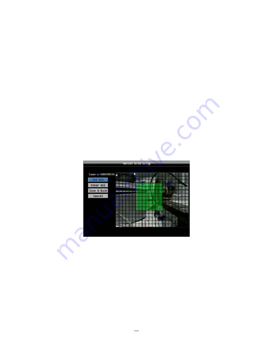
Select the grid square in the lower-right of the desired rectangle. 

4.


The area between upper-left and lower-right grid will be selected. 

The same result is achieved from lower left followed by upper right. 
5.    Choose “Save & Back” to proceed. 

How to select motion grid by front panel: 

1.


Press Enter key on “Grid Setting” to launch motion grid setting page. . 

2.


Use arrow keys to scroll above or below list of buttons to enter the grid setting area. 

3.


Press Enter key to display grid. 

4.


Use arrow keys to choose one corner of desired area 

5.


Press Enter key at the starting point. 

6.


Use arrow keys to select motion area; the shape of the proposed area will be displayed. 

Press Enter key at the end point, and the area will be selected. 
Press the Menu key to exit the area selection; use the up/down arrows to choose “Save & Back” and press 

Enter to proceed.


Click on the “

Search

” button to start searching. The search results will be shown as a list of events. 

Summary of Contents for ENDEAVOR EDRHD-2H14

Page 1: ...User Manual E EN ND DE EA AV VO OR R S SD D H HD D D DV VR R E ED DR R H HD D 2 2H H1 14 4 4 4H H4 4...

Page 2: ...en permission of the Everfocus Electronics Corporation Release Date Feb 2011 QuickTime is a registered trademark of the Apple Computer Inc Windows is a registered trademark of the Microsoft Corporatio...

Page 3: ...y cause electric shock Do not use strong or abrasive detergents when cleaning the appliance body Use a dry cloth to clean the appliance when it is dirty When the dirt is hard to remove use a mild dete...

Page 4: ...they may touch dangerous voltage points or short out parts that could result in a fire or electric shock Never spill liquid of any kind on the unit Rack Mount Instructions The following or similar ra...

Page 5: ...rantee that interference will not occur in a particular installation If this equipment does cause harmful interference to radio or television reception which can be determined by turning the equipment...

Page 6: ...m Output Relay 16 2 4 RS 485 KEYBOARD PTZ INSTALLATION 16 2 4 1 General RS 485 bus installation 17 2 4 2 RS 485 ports 18 2 4 3 EKB 500 connection with network patch cable 18 2 4 4 EKB 500 connection t...

Page 7: ...6 3 12 1 Time Search 37 3 12 2 Event Search 37 3 12 3 Smart Search 38 3 12 4 Snapshot Search 41 3 13 COPY 43 3 14 LOGOUT 44 4 DVR CONFIGURATION 45 4 1 CONFIGURATION MENU 45 4 2 EXPRESS 45 4 3 CAMERA S...

Page 8: ...AL PORTS 103 5 5 PRE INSTALLATION 103 5 6 WHAT IS YOUR NETWORK SETUP 104 5 7 SIMPLE ONE TO ONE CONNECTION 105 5 8 DIRECT HIGH SPEED MODEM CONNECTION 110 5 9 ROUTER OR LAN CONNECTION 112 6 REMOTE OPERA...

Page 9: ...viii APPENDIX C REMOTE CONTROL 139...

Page 10: ...sing and complex network design The ENDEAVOR HD SD DVR is a powerful full featured embedded DVR with all the capabilities familiar front panel controls user friendly mouse driven Graphical User Interf...

Page 11: ...e playing back o Express Search Use the intuitive playback bar with simple drag drop operations o Smart Search Review recorded video to identify motion in area s of interest o Snapshot search choose a...

Page 12: ...x1 User Manual x 1 Power Cord x1 Mouse x 1 19 Rack mounting adapters pair x 1 Terminal Block x 5 IR Remote Control x 1 Battery x 2 Audio in connector D sub to RCA x 1 HDD Fixing Bracket x 4 set SATA c...

Page 13: ...C 100fps PA Mobile View Live view on PDA or Smart Phones MobleFocus FREE app for iPhone and Android plus various web browsers Pentaplex Operation Simultaneous Live Recording Playback Archive and Remot...

Page 14: ...t RS 232 9 pin D Sub socket male RS 485 1 RS485 2 RJ45 connector Power Source 100VAC 240VAC Power Consumption 110W max with 4 x HDD Dimensions L x W x H 423 x 430 x 79 5 mm 16 6 x 16 9 x 3 2 Temperatu...

Page 15: ...th your new DVR will be through the Front Panel buttons and their corresponding buttons on the included IR Remote Control Take a moment to learn where the keys are as the remainder of the manual will...

Page 16: ...tween Main monitor and Call monitor Function reserved 9 Zoom In full screen mode 2x and 4x electronic zoom Zoom screen can be moved through arrow keys Pressing the Menu ESC key again switches the elec...

Page 17: ...nding on playback mode 18 I I Forward playback or pause 19 Stop playback 20 I I Reverse playback or pause 21 I Fast reverse playback or step reverse playback depending on playback mode 22 USB ports Us...

Page 18: ...provided into the power socket 2 ETHERNET RJ 45 network connection 10 100Mbps Ethernet There are two LEDs on the LAN jack Green LED means network is connected amber LED flickers when data is being exc...

Page 19: ...f an audio preamplifier to the audio input connection corresponding to the appropriate camera 10 Audio Out Connect to the line level input of an audio amplifier 11 HD CCTV Video In CH15 16 2H14 only C...

Page 20: ...the camera high frequencies are used for HD CCTV signal transmission EverFocus HD CCTV technology is mostly based on the SMPTE 292M standard which defines HD SDI High Definition Serial Digital Interf...

Page 21: ...he coaxial cable and plug influences signal stability The standard RG 59 cable types the most common in the CCTV industry are originally designed for lower frequencies However due to the new optimized...

Page 22: ...ping HD SDI signals by BNC T connectors to other devices is not possible 2 1 5 BNC plug Also the BNC plug plays an important role for clear HD CCTV signal transmission Standard BNC plugs for CCTV have...

Page 23: ...r single mode max transmission distance 21 Km EHA RTX MM Fiber optics receiver multi mode max transmission distance 500 m EHA RTX SM Fiber optics receiver single mode max transmission distance 21 Km E...

Page 24: ...ease use only high quality HDMI cable 2 2 AUDIO INSTALLATION EDR HD 2H14 DVR provides 16 line level audio inputs and 2 line level audio outputs EDR HD 4H4 provides 8 line level audio inputs and 2 line...

Page 25: ...itched if required Alarm input response actions can be controlled according to a flexible schedule 2 3 1 Alarm Input Contacts This DVR provides one alarm input per camera All inputs are programmable N...

Page 26: ...et Both of these can be expanded using a signal distributor EverFocus Model EDA997A see below Both the first and the last device in series should be terminated with 120 Ohm resistance in order to mini...

Page 27: ...loop through 2 4 3 EKB 500 connection with network patch cable For a simple short distance installation recorder and keyboard can be connected directly using a standard CAT5 network cable with an 8 pi...

Page 28: ...eserve the higher speed front USB V2 0 port for video copy export NOTE Recommended mouse types are Logitech and Microsoft wired USB wheel mouse Wireless USB mouse is not supported 2 6 NETWORK CONNECTI...

Page 29: ...through Patch Cable The connection to an existing network requires a normal patch cable straight through The illustration shows the connection to a network switch or router Figure 2 2 Network Connecti...

Page 30: ...completed the basic wiring connections you are ready to turn on the DVR Simply plug in the power source The POWER LED will light up if power is normal Once the system has finished loading you can beg...

Page 31: ...ected screen will be highlighted by a white frame 2 Double clicking on a channel screen will display full screen for this channel 3 To enable audio out click the audio icon ex at lower side of the scr...

Page 32: ...on a choice to select it 3 In section 3 all the options for the selected choice will be available Click on a field to make changes 3 1 4 Field Input Options The following are examples of different typ...

Page 33: ...r Right Note about on screen keyboard Click on a button to input that character The buttons on the right and bottom have the following functions Space Enter a space Caps Switch to capital letters Dele...

Page 34: ...e menu bar 2 Press Enter key on any icon to perform that action These actions are covered in detail in Chapter 3 3 Press Menu to close the DVR menu bar 2 2 3 Front Panel Key Review The basic principle...

Page 35: ...e Use arrow keys to move between items and press Enter to make changes to that item Note press the Menu button to go back to the previous menu section level 2 2 5 Field Input Options Textbox Press Ent...

Page 36: ...ttons to highlight each character and press the Enter key on the front panel to input the selected characters When finished highlight Done and press the Enter key on the front panel to confirm The but...

Page 37: ...re details 2 If a schedule is active the DVR will follow the record settings of the schedule 3 2 LOGIN In order to access ENDEAVOR SD HD options users may be asked to log in for authority identificati...

Page 38: ...3 3 SELECT CAMERA OPERATION ENDEAVOR SD HD is a pentaplex DVR users can control each camera individually by selecting that camera For camera selection Mouse Right click the screen the image will show...

Page 39: ...back 4 Slow Forward key press to start slow forward playback 5 Fast Reverse key press to start fast reverse playback 6 Reverse key press to start reverse playback 7 Forward key press to start forward...

Page 40: ...ion and angle 2 To Zoom Click Z to zoom closer or Z to zoom farther away 3 To Focus click F to focus far or click F to focus near 4 With Iris you can increase the amount of light by clicking I or decr...

Page 41: ...de the PTZ menu see Express control below Click Exit to leave PTZ function X only HIDES the PTZ control panel EXIT closes the panel and exits PTZ mode Other controls will not respond until you EXIT th...

Page 42: ...12 PTZ pan right 13 PTZ pan tilt left and down 14 15 PTZ tilt down 16 PTZ pan tilt right and down 6 Focus closer 10 Focus further 7 Zoom in 11 Zoom out REMEMBER Click X at the top right corner to hid...

Page 43: ...Press any channel key to bring that channel to full screen mode With a mouse double left click again on the screen to return to the previous multiple camera layout 3 8 CHANNEL SWITCHING Use this func...

Page 44: ...information Please see the following table for status representation Alarm Audio Event HDD failure HD temp too high Seq Motion Video loss No network 4 Press again to show both status information and c...

Page 45: ...e to be displayed by clicking directly on screen Figure 3 4 Zoom Express Control The screen is divided into a 4x4 grid The function of each section is defined as below 1 Left and up 2 3 Up 4 Right and...

Page 46: ...e and Time Click on the Play button to start the search The DVR will automatically begin to play the video selected The DVR will play the nearest time if there is no data at the selected time In searc...

Page 47: ...rev Page Go to previous page Next Page Go to next page Play Playback selected item Copy Copy selected item Note Text Search supported by VSI Pro Max POS Cash register interface from AVE has been imple...

Page 48: ...the motion grid See Figure 4 5 Camera Menu Motion Grid Setting Set All Press this button to select the entire area Clear All Press this button to clear all the grids selected Save Back Press this but...

Page 49: ...to scroll above or below list of buttons to enter the grid setting area 3 Press Enter key to display grid 4 Use arrow keys to choose one corner of desired area 5 Press Enter key at the starting point...

Page 50: ...e Go to next page Play Playback selected item Copy Copy selected item 3 12 4 Snapshot Search Snapshot Search shows snapshots of the specified interval it helps users to quickly find the interested sce...

Page 51: ...il will be the interval set in Result Interval next to the first thumbnail and so on If forward is selected as search direction a white frame will surround the selected snapshot at the first thumbnail...

Page 52: ...ved Choose Select All to select all the cameras Player Check the box to include the ePlayer program as part of the copy recommended Start Date Time Select the starting date time to be archived End Dat...

Page 53: ...click the button to bring up the Logout Confirmation window see Figure 3 11 Figure 3 11 Logout Confirmation window Press Yes button when you are ready to logout from the system You will need to login...

Page 54: ...n icon to enter the Configuration Menu Log in if necessary see Section 3 2 LOGIN above 4 2 EXPRESS The Figure 4 1 Express Menu is a screenshot of the EXPRESS SETTING MENU This menu is used to configur...

Page 55: ...nt recording Event Only Event recording only Schedule Rec Schedule recording For Event recording enter the estimated number of hours per day for event recording Main Resolution Select recording resolu...

Page 56: ...be assigned automatically Subnet Mask This field shows the subnet mask for your network so the DVR will be recognized within the network If DHCP or PPPoE is selected this value will be assigned automa...

Page 57: ...Camera Select the camera to be configured Title The title setting allows you to assign a title to the selected camera Each title supports up to 16 characters The on screen keyboard will appear when yo...

Page 58: ...rd Basic and Low A higher image quality uses more HDD space Normal Speed Main Stream Sub Stream Frame rate in frames images per second FPS for continuous recording The speed is limited by the maximum...

Page 59: ...D is ON a drop down menu will appear set the PTZ ID address used to control this camera in that menu Apply To This button can be used to copy the recording settings to other cameras Select which camer...

Page 60: ...ly To This button can be used to copy the video settings to other cameras Select which cameras you wish to copy to Select All selects all cameras Unselect All deselects all cameras Click OK to copy th...

Page 61: ...ion is triggered Timeout Alarm output lasts for a set of time duration If this option is selected a field will appear for setting the duration Permanent Alarm will remain on until the user presses the...

Page 62: ...y grid 4 Use arrow keys to choose one corner of desired area 5 Press Enter key at the starting point 6 Use arrow keys to select motion area the shape of the proposed area will be displayed 7 Press Ent...

Page 63: ...mera Enable Check box to enable Video Loss detection Log Check box to record video loss events in the log Pre alarm Record Check box to start copying recorded video to the hard disk from 5 seconds bef...

Page 64: ...o either NONE not active 1 2 3 or 4 indicating which alarm relay is active Output Type Output action when alarm is triggered Timeout Alarm output lasts for a set time duration If this option is select...

Page 65: ...e DVR from recording is to turn schedule recording off Pressing any key on the front panel to attempt to stop recording will not work during scheduling record mode When schedule recording is disabled...

Page 66: ...please enter your expectations for the hours per day you expect recording to take place due to motion events and due to other alarm conditions Figure 4 8 Record Play Menu Built in Cal Motion Enter th...

Page 67: ...unction as described below Playback From X Seconds ago When the DVR is put into playback press PLAY it will begin playing from the selected time Choose from 60 to 3600 seconds prior to the present tim...

Page 68: ...nds before the alarm event Pre alarm recording rate will follow the Normal frame rate setting Buzzer Check this box to enable the buzzer when an alarm occurs Main Monitor Main monitor display options...

Page 69: ...ON a sub menu is displayed for choosing the desired PTZ preset number Auto Lock Check the box and the events will be recorded in the write protected segment of the Hard Disk DVR will lock a period of...

Page 70: ...If the DVR is not set to Overwrite in the Record Menu an event will be created when the HDD is filled HD Off If HDDs are switched off or are removed the DVR will create an HD OFF event Power Loss If p...

Page 71: ...il settings have been entered in the Network Setting Email setup screen Network Alarm Check box to send out a network alarm to client PC requires PowerCon software and setting up Alarm Server in Netwo...

Page 72: ...Network Alarm Check box to send out a network alarm to client PC requires PowerCon software and setting up Alarm Server in Network Setup menu Stop Recording Check box to stop recording when HD s temp...

Page 73: ...id email settings have been entered in the Network Setting Email setup screen Network Alarm Check box to send out a network alarm to client PC requires PowerCon software and setting up Alarm Server in...

Page 74: ...software and setting up Alarm Server in Network Setup menu Alarm Output This will transmit a signal through the alarm output It can be set to either NONE not active 1 active 2 active 3 active or 4 ac...

Page 75: ...ftware and setting up Alarm Server in Network Setup menu Alarm Output This will transmit a signal through the alarm output relay It can be set to either NONE not active 1 active 2 active 3 active or 4...

Page 76: ...ail operation requires that valid email settings have been entered in the Network Setting Email setup screen Network Alarm Check box to send out a network alarm to client PC when power has been restor...

Page 77: ...utput lasts for the set time duration Permanent Alarm will be continuously active until user presses Enter key Transparent Alarm output remains active until event ends Trans Timeout Alarm output conti...

Page 78: ...ct weekday daytime starting time Nighttime schedule ends when Daytime begins Daytime End Select weekday daytime ending time Nighttime schedule begins when Daytime ends Record Type Select the type of r...

Page 79: ...ing up a confirmation window Select Yes to confirm and apply the express schedule settings or No to cancel changes 4 6 2 Holidays In addition to setting a weekly record schedule user can also schedule...

Page 80: ...camera recording mode by time of day on specific days of the week and or holidays and other days Figure 4 22 Schedule Menu Schedule Camera Select a camera number to change the schedule for that camera...

Page 81: ...switches from gray orange blue every time the user clicks the first block of a section 4 Repeat clicking on the first block indicated by a sequence number on it of any timezone this timezone will chan...

Page 82: ...a red frame See below image Use Up Down arrow key to select the desired time bar for setting 6 Editing blocks in a time bar when a time bar is selected highlighted in red frame press the Enter button...

Page 83: ...another record mode The color switch sequence is gray orange blue 8 To exit the screen press the Menu Esc button as required to move up the menu levels and if desired out of the menu system Click the...

Page 84: ...1280x720 sized framed per second Thus the DVR can record a combination of CIF 2 CIF and 4 CIF images with different combinations of image size resolution and different FPS rates on different cameras s...

Page 85: ...On Alarm action will be recorded during this time block To Set Schedule using Mouse 1 Click on the Alarm Action choice then click on the right hand side of the screen The border for that region will n...

Page 86: ...ction menu choice and press the Enter button to enter Alarm Action setting mode At this time the whole editing area at the right side will be highlighted within a blue frame See image below 2 Enter al...

Page 87: ...et to the recording mode of gray Alarm Action off User can also change the timezone to a different record mode by following instructions in the next step 7 Changing recording mode color of a timezone...

Page 88: ...s button can be used to copy schedules to other cameras Select which cameras you wish to copy to Select All selects all cameras Clear All deselects all cameras Click OK to copy the settings or Cancel...

Page 89: ...the DVR s current IP Address A static IP address must be set manually If DHCP or PPPoE is selected this value will be assigned automatically Subnet Mask This field shows the subnet mask for your netw...

Page 90: ...f the local DNS server The DNS server IP is required because your DNS server provides critical information necessary for the DVR to communicate with the DDNS server You can obtain the actual DNS IP fr...

Page 91: ...bled 128 K 256 K 512 K 768K 1M 3M bps This is the maximum bandwidth that the DVR is allowed to use on the network This is a useful function when connecting the DVR to busy or heavily loaded networks o...

Page 92: ...nput the second e mail address that event messages are sent to Receiver Email 3 Input the third e mail address that event messages are sent to Email Subject Input email subject 4 7 3 DDNS DDNS Server...

Page 93: ...ge instead double check your network settings and DDNS name and resubmit the DDNS name until you get Success You should now be able to connect by typing in the host name you created Example http hostn...

Page 94: ...f client PC with installed PowerCon Software The network alarm can be transmitted to up to 3 addresses Protocol Select the protocol type for alarm transmission UDP User Datagram Protocol TCP Transmiss...

Page 95: ...86 4 7 5 Network Test Figure 4 30 Network Menu Alarm Server Enter the server s IP address to be tested Press Ping button to ping the IP address...

Page 96: ...4 8 1 Disk Record Time Start Shows earliest recorded time on the DVR Record Time End Shows latest or most current recorded time on the DVR Disk Select disk number Health Status Displays current status...

Page 97: ...aximum lock percentage of the HDD volume After setting the lock percentage conditions where video is written to the locked area can be enabled disabled in three places i Camera Basic Setting Motion Au...

Page 98: ...lay camera titles Date Time Check the box to display current date time Event Status Check the box to display event status HDD Status Check the box to display hard drive status Playback Date Time Check...

Page 99: ...Q Step Sequence order For reference Camera Select which camera appears in the current step Dwell sec Set the dwell time for each step Sequence dwell time can be set from 0 to 99 seconds Sequence repea...

Page 100: ...pdating from the time server NTP Select Enable or Disable NTP time synchronization NTP Server Displays the time server address that the DVR uses for time synchronization Requires operating network con...

Page 101: ...ving time begins Set To hh mm This is what the time will change to when daylight saving begins For most regions this will be one hour ahead of the Start Time End Date Set the end date for daylight sav...

Page 102: ...the charts below for a listing of the rights associated with each access level Figure 4 36 System Menu User Add Click Add button to add a new user Set the name case sensitive password access level an...

Page 103: ...u User Edit User Login Check this box to require user login for menu access from the front panel When this is disabled no username or password is required to access the system from the front panel and...

Page 104: ...Search OK OK NO Copy OK OK NO Config OK OK OK View Covert Cameras OK OK NO Logout OK OK OK Configuration Menu at the DVR User Level and Right RIGHT ADMINISTRATOR MANAGER OPERATOR Express OK NO NO Came...

Page 105: ...gh the RS232 port on the DVR There are eight different speeds 1200 BPS 2400 BPS 4800 BPS 9600 BPS 19200 BPS 38400 BPS 57600 BPS and 115200 BPS Data Bit This field is the data bit at which you will be...

Page 106: ...to 8 or 7 Stop Bit This field is to set the number of stop bits indicating the end of a data packet This can be set to 1 or 2 Parity This selects the transmission error checking rule Choose either No...

Page 107: ...r Configurations Load Factory Default Click Load to restore all menu settings to the default values User Account Network IP Settings and Time are not affected 3GP streaming is disabled by default Load...

Page 108: ...video format on Camera 1 input at boot up Network IP Displays the DVR s current IP Address as set in the Network or Express Setup screen MAC Unique address of the DVR s internal network card This opti...

Page 109: ...to be displayed Log Type Configurations to see log entries related to configuration changes Event to see log entries related to events Record to see log entries related to recording changes Operation...

Page 110: ...101 Figure 4 44 Log List Prev Page Go to the previous page of log Next Page Go to the next page of log Close Close the window...

Page 111: ...ree octets of an IP address is often the same for all computers in the local area network For example if a total of 253 computers exist in a single LAN the IP addresses could be assigned starting with...

Page 112: ...A port can refer to Ethernet connection points such as those on a hub switch or router The term port is also used to refer to a physical connection point for peripheral devices such as serial paralle...

Page 113: ...your IP address changes each time you connect to the Internet We recommend asking your Internet service provider for a Static IP address If this is not a possibility you may use the DDNS feature of th...

Page 114: ...setup described below 3 Router or LAN Connection A local area network connection requires either a router or a pre existing LAN connection This is the most common type of connection A router allows m...

Page 115: ...R and the other into the network card on the back of the computer Log into the EverFocus DVR menu and go to the Network Setting Menu You must use the Static IP option for this type of connection Assig...

Page 116: ...107...

Page 117: ...108...

Page 118: ...sign an IP address of 192 168 1 2 a Subnet Mask of 255 255 255 0 and a Default Gateway of 192 168 1 1 then click OK Restart both the computer and the DVR To access the DVR from the computer simply ope...

Page 119: ...ocedure The first step is to purchase or make a straight through cable We recommend purchasing one if you have never made a straight through cable Please remember you can not use a cross over network...

Page 120: ...to automatically detect the network settings Therefore it can use a dynamic IP address Exit from the DVR s Menu to save the settings To access the DVR from a computer open Internet Explorer and in th...

Page 121: ...shows the pin configurations for a straight cable Connection Procedure The First step is to purchase or make a straight through cable We recommend purchasing one if you have never made a straight thr...

Page 122: ...a computer connected on the same network as the DVR Click on the Start button and choose Run o If using Windows Vista choose Search instead Type command and click on OK o In Vista you will need to dou...

Page 123: ...open 80 o If your Internet service provider blocks port 80 you can change it to a different port in the DVR s Network Menu Setup open forward that port instead o If you are using a Linksys or D Link r...

Page 124: ...ress bar type Local connection http IP address from the DVR s Network Menu IP port used e g http 192 168 1 163 2468 Internet connection http IP address given by your Internet Service Provider IP port...

Page 125: ...ill log in to the recorder s Network Viewer 6 2 BROWSER SECURITY SETTING 6 2 1 Installing ActiveX controls When you first connect to the DVR s IP address you should see a screen like the one below If...

Page 126: ...117 Install the ePlusDVR cab file when prompted to do so Once the file finishes installing you will return to the screen like the one below...

Page 127: ...118 Right click on the yellow bar and select Run Add on Install the MSXML file when prompted to do so Now you will able to see the remote live page...

Page 128: ...NOT see the yellow ActiveX bar at the top of your browser screen when you first connect to the DVR At the top of the Internet Explorer Window click on Tools then select Internet Options Click the Sec...

Page 129: ...rols Binary and script behaviors Display video and animation on a webpage that does not use external media player IE7 only Run ActiveX controls and plug ins Script ActiveX controls marked safe for scr...

Page 130: ...all the ePlusDVR cab file when prompted to do so Once the file finishes installing you will return to the same login page as before Type in the user name and password and click Login to view the camer...

Page 131: ...e to enlarge the current display to full screen double click again or press Esc to return to the normal view 3 Main Sub Click this icon to switch stream for multi view Sub stream image is less clear a...

Page 132: ...tup Alarm Setup Schedule Setup Network Setup Hard Disk Setup Display Setup System Setup Information Setup Video Export Playback Search PTZ Control 6 In the main page you will see live images in a 16 s...

Page 133: ...t Search setting please refer to 3 12 Search Setting Event Search and Motion Search will show maximum 400 search result items beginning with the start time Playback Control Keys 1 Fast rewind the vide...

Page 134: ...and attempt to register that name must fail If the name is available proceed to step 3 for DDNS setup Step 3 In DVR s Network Menu go to DDNS Choose EverfocusDDNS for the Server and put in your chosen...

Page 135: ...uld now be able to connect by typing the name you created into the address bar Example http hostname everfocusddns com It is not necessary to append the HTTP port number to the DDNS name The EverFocus...

Page 136: ...nch a web browser and type the Router s IP address typically 192 168 1 1 in the address bar Then press Enter A password request page will appear Non Windows XP users will see a similar screen Leave th...

Page 137: ...nd the ending number under End Protocol Enter the protocol used for this application either TCP or UDP or Both IP Address For each application enter the IP Address of the PC running the specific appli...

Page 138: ...f you need additional technical support on this router you must call D Link Whenever you want to configure your network or the DI 624 you can access the Configuration Menu by opening a web browser and...

Page 139: ...virtual service Private IP The IP address of the device running the local services Protocol Type The protocol used for the virtual service Private Port The port number that the service uses on the LA...

Page 140: ...e IP Protocol Private Port Public Port Schedule HTTP 192 168 1 50 Both 80 80 Enable Where 192 168 1 50 is the IP address of the ENDEAVOR SD HD on the LAN and the default port 80 is in use Note If you...

Page 141: ...ect input source and display setting 1024x768 Check that the monitor cables are good and power is on Verify the recorder is getting the correct supply power There is no display coming from one of the...

Page 142: ...133 Make sure you are using the correct WAN IP address given by the ISP or if you have a Dynamic IP check if the IP address has changed use DDNS to avoid problems caused by changing ISP addresses...

Page 143: ...alarm mode related to event record alarm outputs OSD message buzzer Timeout Transparent Mode t Input Event Alarm Duration t Duration t Reaction t Event t Event Duration of alarm input source motion co...

Page 144: ...tion Resulting duration for this alarm mode related to event record alarm outputs OSD message buzzer Permanent Mode t Input Event Alarm Duration t Reaction t Event Alarm Reset t Event Duration of alar...

Page 145: ...Resulting duration for this alarm mode related to event record alarm outputs OSD message buzzer Timeout Transparent Mode Retrigger of Alarms t Event Duration of alarm input source motion contact syste...

Page 146: ...Checking Order 1 2 3 4 5 6 7 8 Normal Frame Rate 1 1 1 1 1 1 1 1 Quality Superior Standard Low Low Low Low Low Low Event Frame Rate 30 30 30 15 10 7 5 5 1 Case 2 Record Mode Event Only Record With Rec...

Page 147: ...o the Preset Settings Preset Setting Option Camera Item Apply value Quality Superior Normal Frame Rate Max recording frame rate of DVR Best Quality Event Frame Rate 30 Quality Standard Normal Frame Ra...

Page 148: ...trol The effective distance is up to 33 feet line of sight The keypad functions are same as the front panel buttons of the DVR Appendix C ID number here must correspond to the IR Remote ID in I O Cont...

Page 149: ...89 www everfocus co jp info everfocus co jp EverFocus Europe UK Unit 12 Spitfire Business Park Hawker Road Croydon Surrey CR0 4WD UK TEL 44 20 8649 9757 44 845 430 9999 FAX 44 20 8649 9907 www everfoc...

Reviews: