background image

42  …………………………………………………………………….  INSTRUCTION MANUAL


▶ 

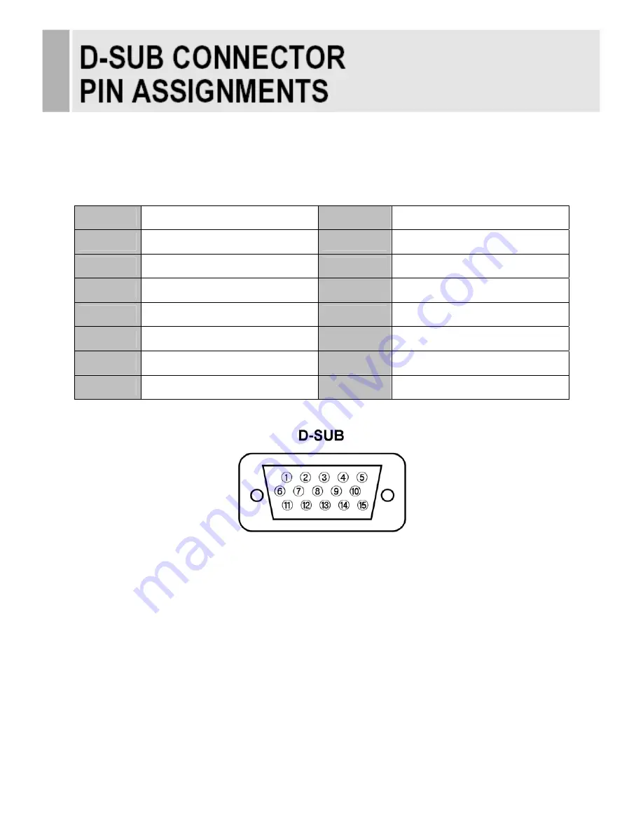
PIN ASSIGNMENTS


Pin 1 

RED VIDEO 


2 GREEN 

VIDEO 

10 

SIGNAL CABLE DETECT 

3 BLUE 

VIDEO 

11 GROUND 

4 GROUND 

12 SDA(for 

DDC) 

5 GROUND 

13 

H-SYNC.(or H+V SYNC.) 

6 RED 

GROUND 

14 V-SYNC. 

7 GREEN 

GROUND 

15 SCL(for 

DDC) 

8 BLUE 

GROUND 


▶ 

ACCESSORIES


1. Power cord 
2. Power adaptor 
3. User’s manual 
4. PC cable 
5. Trigger cable (Option) 
6. Stereo cable (Option) 
7. Remote controller (Option) 
8. Batteries (Option) 
9. Wall mount (Option) 


Summary of Contents for EN-7522C

Page 1: ...Instruction Manual EN 7522C 22 Wide Screen TFT LCD Monitor...

Page 2: ...eference SAFETY INSTRUCTION 2 3 CAUTIONS 4 FCC RF INTERFERENCE STATEMENT 5 CONNECTING WITH EXTERNAL EQUIPMENT 6 REMOTE FUNCTIONS 7 CONTROLS AND FUNCTIONS 8 41 MOUNTING GUIDE 42 D SUB CONNECTOR PIN ASS...

Page 3: ...rized plug has two blades with one wider than the other Agrounding type plug has two blades and a third grounding prong The wide blade or the third prong are provided for your safety If the provided p...

Page 4: ...to rain or moisture does not operate normally or has been dropped 2 INSTRUCTION MANUAL The apparatus shall not be exposed to dripping or splashing and that no objects filled with liquids such as vase...

Page 5: ...ence of important operating and maintenance servicing instructions in the literature accompanying the appliance INSTRUCTION MANUAL 3 CAUTION The power supply cord is used as the main disconnect device...

Page 6: ...pliance TO ELIMINATE EYE FATIGUE Do not use the unit against a bright back ground and where sunlight or other light sources will shine directly on the monitor BE CAREFUL OF HEAVY OBJECT Neither the mo...

Page 7: ...d receiver Connect the equipment into an outlet on a circuit different from that to which the receiver is connected Consult the dealer or an experienced radio TV technician for help Only shielded inte...

Page 8: ...2 IN 3 VIDEO1 AV1 OUT 4 VIDEO1 AV1 IN 5 TRIGGER INPUT 6 7 AUDIO IN R L for AV1 AV2 and S VIDEO 8 S VIDEO Y C IN 9 AUDIO OUT Speaker 10 PC STEREO IN 11 VGA D SUB IN 12 DVI IN 13 HDMI IN 14 DC 12V IN 6...

Page 9: ...r selection or displays the current mode 11 INFO Input mode information Display 12 STILL Stop the picture 13 PIP Picture In Picture Activate PIP mode 14 P INPUT Change source of sub picture in PIP mod...

Page 10: ...is HOLD function and stop the Trigger Auto switching functions 5 6 VOL Adjust the volume and menu settings 7 POWER ON OFF I Turns the power ON or OFF There will be a few seconds delay before the displ...

Page 11: ...b menu 3 Press the left or right button to adjust the picture setting 4 Press the MENU button to save Brightness Increase or decrease the intensity of the image Contrast Increase or decrease the inten...

Page 12: ...PC HDMI Input 1 Press the MENU button and then press the up or down button to select the Custom 2 Press the up or down button to select the sub menu 3 Press the left or right button to adjust the pict...

Page 13: ...10 INSTRUCTION MANUAL B Picture Sound Menu Only Video Input 1 Picture Mode...

Page 14: ...tton to select the Picture Sound 2 Press the right or SOURCE button 3 Press the up or down button to select the Picture Mode 4 Press the right or SOURCE button 5 Press the up or down button to select...

Page 15: ...INSTRUCTION MANUAL 11 2 1 Color Tone 1 Press the up or down button to select the Color Tone 2 Press the right or SOURCE button...

Page 16: ...3 Press the right or SOURCE button again 4 Press the up or down button to select the Color Tone option 5 Press the MENU button to save 12 INSTRUCTION MANUAL 2 2 Color Tone User...

Page 17: ...down button to select the User 2 Press the MENU button 3 Press the up or down button to select the User option 4 Press the left or right button to adjust the Red Green or Blue setting 5 Press the MEN...

Page 18: ...INSTRUCTION MANUAL 13 3 Mute 1 Press the up or down button to select the Mute 2 Press the right or SOURCE button 3 Press the up or down button to select the On or Off 4 Press the MENU button to save...

Page 19: ...14 INSTRUCTION MANUAL 4 Volume 1 Press the up or down button to select the Volume 2 Press the left or right button to adjust Volume setting 3 Press the MENU button to save...

Page 20: ...INSTRUCTION MANUAL 15 5 Size 1 Press the up or down button to select the Size 2 Press the right or SOURCE button...

Page 21: ...3 Press the up or down button to select the Size option 4 Press the MENU button to save 16 INSTRUCTION MANUAL 6 NR Noise Reduction...

Page 22: ...1 Press the up or down button to select the NR 2 Press the right or SOURCE button 3 Press the up or down button to select the On or Off 4 Press the MENU button to save...

Page 23: ...STRUCTION MANUAL 17 7 3D Comb 1 Press the up or down button to select the 3D Comb 2 Press the right or SOURCE button 3 Press the up or down button to select the On or Off 4 Press the MENU button to sa...

Page 24: ...TRUCTION MANUAL B Picture Sound Menu For RGB PC HDMI Input 1 Size 1 Press the up or down button to select the Size 2 Press the right or SOURCE button 3 Press the up or down button to select the Size o...

Page 25: ...INSTRUCTION MANUAL 19 2 PC Only RGB PC Input 1 Press the up or down button to select the PC...

Page 26: ...utton to adjust the PC setting 6 Press the MENU button to save Auto Adjust Auto geometry adjustment Phase Adjust the number of horizontal picture elements H Position Move image horizontally on screen...

Page 27: ...Press the MENU button and then press the up or down button to select the PIP 1 PIP 1 Press the right or SOURCE button 2 Press up or down button to select the On or Off 3 Press the MENU button to save...

Page 28: ...to select the Input Source 2 Press the right or SOURCE button 3 Press the up or down button to select the Source option 4 Press the MENU button to save Possible PIP Combination Main Sub Video Video Vi...

Page 29: ...B PC or HDMI 22 INSTRUCTION MANUAL 3 PIP Mode 1 Press the up or down button to select the PIP Mode 2 Press the right or SOURCE button 3 Press the up or down button to select the PIP Mode option 4 Pres...

Page 30: ...PBP1 Main image Sub image PBP2 Main image Sub image INSTRUCTION MANUAL 23 4 PIP Size...

Page 31: ...1 Press the up or down button to select the Size 2 Press the right or SOURCE button 3 Press the up or down button to select the Size option 4 Press the MENU button to save...

Page 32: ...the up or down button to select the Position 2 Press the right or SOURCE button 3 Press the up or down button to select the Position option 4 Press the MENU button to save RB Right of Bottom LB Left...

Page 33: ...INSTRUCTION MANUAL 25 6 Swap 1 Press the up or down button to select the Swap 2 Press the right or SOURCE button to swap the main image for the sub one...

Page 34: ...26 INSTRUCTION MANUAL 7 Sound Select 1 Press the up or down button to select the Sound Select...

Page 35: ...2 Press the right or SOURCE button 3 Press the up or down button to select the Sound Select option 4 Press the MENU button to save INSTRUCTION MANUAL 27 D Setup Menu...

Page 36: ...e up or down button to select the Setup 1 Reset 1 Press the right or SOURCE button 2 Press the right or SOURCE button again 3 Press SOURCE button to execute the reset Reset All settings go to the fact...

Page 37: ...Language 1 Press the up or down button to select the Language 2 Press the right or SOURCE button 3 Press the up or down button to select language 4 Press the MENU button to save INSTRUCTION MANUAL 29...

Page 38: ...Tone 1 Press the up or down button to select the OSD Tone 2 Press the right or SOURCE button 3 Press the up or down button to select the OSD Tone option 4 Press the MENU button to save 30 INSTRUCTION...

Page 39: ...Screen 1 Press the up or down button to select the Blue Screen 2 Press the right or SOURCE button 3 Press the up or down button to select the On or Off 4 Press the MENU button to save INSTRUCTION MAN...

Page 40: ...ey Lock 1 Press the up or down button to select the Key Lock 2 Press the right or SOURCE button 3 Press the up or down button to select the On or Off 4 Press the MENU button to save 32 INSTRUCTION MAN...

Page 41: ...er 2 Press the right or SOURCE button 6 1 Trigger Enable 1 Press the up or down button to select the Trigger Enable 2 Press the right or SOURCE button 3 Press the up or down button to select the On or...

Page 42: ...ut 1 Press the up or down button to select the Trigger Input 2 Press the right or SOURCE button 3 Press the up or down button to select the Trigger Input option 4 Press the Menu button to save 34 INST...

Page 43: ...3 Buzzer 1 Press the up or down button to select the Buzzer 2 Press the right or SOURCE button 3 Press the up or down button to select the On or Off 4 Press the Menu button to save INSTRUCTION MANUAL...

Page 44: ...6 4 Trigger Time 1 Press the up or down button to select the Trigger Time 2 Press left or right button to adjust Trigger Time setting 3 Press the MENU button to save 36 INSTRUCTION MANUAL...

Page 45: ...r Option setting 4 Press the Menu button to save N C Normal Closed When Trigger cable is opened Trigger function is activated N O Normal Opened When Trigger cable is closed Trigger function is activat...

Page 46: ...the Display Type option 4 Press the Menu button to save PIP FULL When the condition is below the Trigger Input image will be displayed as PIP Main Trigger Input Video Video Video RGB PC or HDMI RGB P...

Page 47: ...button to select the Auto switching 2 Press the right or SOURCE button 7 1 Auto switching On Off 1 Press the right or SOURCE button 3 Press the up or down button to select the On or Off 4 Press the Me...

Page 48: ...on to select the Inputs enabled 2 Press the right or SOURCE button 3 Press the up or down button to select the Input 4 Press the right or SOURCE button 5 Press the up or down button to select the On o...

Page 49: ...7 3 Auto switching Time 1 Press the up or down button to select the Time 2 Press the left or right button to adjust the Time setting 3 Press the MENU button to save INSTRUCTION MANUAL 41...

Page 50: ...the 100 100mm hole pattern on the back panel to install the LCD monitor to the wall Wall mount Installation Option 1 The Monitor fixing bracket to the monitor using the fixing screws provided 2 The m...

Page 51: ...GROUND 4 GROUND 12 SDA for DDC 5 GROUND 13 H SYNC or H V SYNC 6 RED GROUND 14 V SYNC 7 GREEN GROUND 15 SCL for DDC 8 BLUE GROUND ACCESSORIES 1 Power cord 2 Power adaptor 3 User s manual 4 PC cable 5...

Page 52: ...aling system through not sending horizontal vertical or sync signal This monitor enters an appropriate mode through identifying each of the three modes of the signaling system POWER CONSUMPTION MODE P...

Page 53: ...ANGLE 160 160 H V LCD Type RESPONSE TIME 5msec Typical RESOLUTION H x V 1680X1050 60Hz FREQUENCY HORIZONTAL 31 80KHz VERTICAL 56 75Hz VIDEO 2ch input 1 0Vp p 75 terminated loop through out S VIDEO 1c...

Page 54: ...PACKING DIMENSIONS W x D x H 650 mm X 205 mm X 545 mm 25 59 X 8 07 X 21 45 Net Weight 5 83kg 12 83 Ibs WEIGHT Gross Weight 8 42kg 18 52 Ibs ELECTRICAL RATINGS DC 12V 5 83A NOTE Technical specification...

Page 55: ...the environment or human health from uncontrolled waste disposal please separate this from other types of wastes and recycle it responsibly to promote the sustainable reuse of material resources House...

Page 56: ...duct is designed and manufactured with high quality materials and components which can be recycled and reused This symbol means that electrical and electronic equipment at their end of life should be...

Reviews: