background image


Precautions


1.


Do


not


install


the


camera


near


electric


or


magnetic


fields.


Install


the


camera


away


from


TV/radio


transmitters,


magnets,


electric


motors,


transformers


and


audio


speakers


since


the


electromagnetic


fields


generated


from


these


devices


may


distort


the


video


image


or


otherwise


interfere


with


camera


operation.


2.


Never


disassemble


the


camera


beyond


the


recommendations


in


this


manual


nor


introduce


materials


other


than


those


recommended


herein.


Improper


disassembly


or


introduction


of


corrosive


materials


may


result


in


equipment


failure


or


other


damage.


3.


Try


to


avoid


facing


the


camera


toward


the


sun

.


In


some


circumstances,


direct


sunlight


may


cause


permanent


damage


to


the


sensor


and/or


internal


circuits,


as


well


as


creating


unbalanced


illumination


beyond


the


capability


of


the


camera


to


compensate.


4.


Keep


the


power


cable


away


from


water


and


other


liquids


and


never


touch


the


power


cord


with


wet


hands.


Touching


a


wet


power


cord


with


your


hands


or


touching


the


power


cord


with


wet


hands


may


result


in


electric


shock.


5.


Never


install


the


camera


in


areas


exposed


to


oil,


gas


or


solvents.


Oil,


gas


or


solvents


may


result


in


equipment


failure,


electric


shock


or,


in


extreme


cases,


fire.


6.


Cleaning.


For


cameras


with


interchangeable


lenses,


do


not


touch


the


surface


of


the


sensor


directly


with


the


hands.


Use


lens


tissue


or


a


cotton


tipped


applicator


and


ethanol


to


clean


the


sensor


and


the


camera


lens.


Use


a


damp


soft


cloth


to


remove


any


dirt


from


the


camera


body.


Please


do


not


use


complex


solvents,


corrosive


or


abrasive


agents


for


cleaning


of


any


part


of


the


camera.


7.


Do


not


operate


the


camera


beyond


the


specified


temperature,


humidity


or


power


source


ratings.


This


camera


is


suitable


for


indoor


operation


only.


Use


the


camera


at


temperatures


within

 ‐

10°C~50°C


(

14°F~122°F)


and


humidity


less


than


80%;


this


device


is


not


rated


as


submersible.


The


input


power


source


is


12VDC.


Be


sure


to


connect


the


proper


+


/

 ‐ 

polarity


and


voltage,


as


incorrect


polarity


or


too


high


a


voltage


will


likely


cause


the


camera


to


fail,


and


such


damage


is


not


covered


by


the


warranty.


8.


Mounting.


Use


care


in


selecting


a


solid


mounting


surface


which


will


support


the


weight


of


the


camera


plus


any


wind,


snow,


ice


or


other


loading,


and


securely


attach


the


camera


to


the


mounting


surface


using


screws


and


anchors


which


will


properly


support


the


camera.


If


necessary


(e.g.


when


mounting


to


drop


ceilings)


use


a


safety


wire


to


provide


additional


support


for


the


camera.


Summary of Contents for EMD935F

Page 1: ...EM 10 O MD9 080p utdo 935F p Ful oor IP l Hig P66 M Co gh De Mobi pyright E Releas efini ile IR EverFocus E se Date Ma ition R Min lectronics C y 2016 ni Ba U Corp ll Ca User s M mera Manual a...

Page 2: ...ts may result in equipment failure electric shock or in extreme cases fire 6 Cleaning For cameras with interchangeable lenses do not touch the surface of the sensor directly with the hands Use lens ti...

Page 3: ...er s authori t 15 of the ay not cause luding inter 3 afety No terference S nd to comp ese limits ar tial installat ot installed a communica r installation tion which to correct t ntenna e equipmen le...

Page 4: ...4 Contents 1 INTRODUCTION 5 1 1 PACKING LIST 5 1 2 FEATURES 5 2 CABLE DESCRIPTION 6 3 INSTALLATION 7 3 1 INSTALLATION AND ADJUSTMENT 7 4 CONFIGURATION IN THE OSD MENU 10 5 SPECIFICATIONS 14...

Page 5: ...ty from the p to 10M 33 vers amazin visibility un sures less bl w light enviro 960H ana Control cam x 1 EM 5 ipped with tured with t es even und allows wall h 6 IR LEDs d outdoor e be switched and pe...

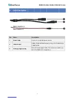
Page 6: ...Cable Desc Conn 1080 coax Opti whil EM 6 criptions nects to a 1 0p 720p an xial cable onal power e the black MD935F Out 12VDC powe nd 960H out r pigtail cab wire is neg tdoor Mobi er source tput usin...

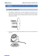
Page 7: ...o screws ustment all Mount us mera drill th other hole in ng using the s EM 7 sers Stick t ree holes o n the temp supplied hex MD935F Out he template on the temp late plate o xagon wren tdoor Mobi e p...

Page 8: ...k to ba cable wirin om the Side base ody no need r selected t EM 8 e wall ceil ase plate wi ng as follow e d to be lock the suited a MD935F Out ling using th th supplied ing illustrat Wir ked too tigh...

Page 9: ...angle t o base plate using the s lens and on esigned for road EM 9 C power sou ng the video hen tighten e and one o supplied two ne on each s r protecting MD935F Out rce using th o out cable n the two...

Page 10: ...lay Black Mask Level Model Default EM 10 enu D menu from Function 0 1 60 FL 50000 X2 1 50 FLK 50000 X2 Sens u Level Pos Si Grada Defau Middle Positio Area1 Off On k On Of 0 100 All Day Night MD935F Ou...

Page 11: ...00 y 0 60 y 0 60 1 255 y 0 60 1 255 y 0 60 Off On Off On 0 100 w Off High w Off High 01234 Off On Off M e Off On Select Displa Sensit Color Trans Alarm MD935F Out n Lev Are 456789ABCD _ n Mirror V fli...

Page 12: ...Sta DP Lev AG Se Po Sta DP Lev n tdoor Mobi me ea1 Area2 A f lor osaic v hite Black llow Green 00 0 75 0 50 25 SPA POL RU GC level vel s Size art PC View vel GC ns up s Siz art PC View vel ile IR Mini...

Page 13: ...strate your operat White Bala EM 13 2400 4 Level Start A End AG Black Blue G Red G Gamm Blue G Red G D Reset No tion environ egy tion environ egy tion environ ance strateg MD935F Out 4800 9600 1 0 1 A...

Page 14: ...ct to cha MD935F 2 9 Sony 2 TSC and PA 920 H x108 rogressive S lux with IR UTO Manu 45 6mm Fixed OFF HSBLC B 15 Levels TW AWC S nternal xt Auto Co Units p to 10m 3 2 Language DNR 3DNR Off Auto On Off...

Page 15: ...s d fe ur Ihr EverFocus Pr entwickelt und h qualitativ hochw und Komponente wieder verwende Dieses Symbol b elektrische und e am Ende ihrer N Hausm ll getren sollen Bitte entsorgen S Ihrer rtlichen k...

Reviews: