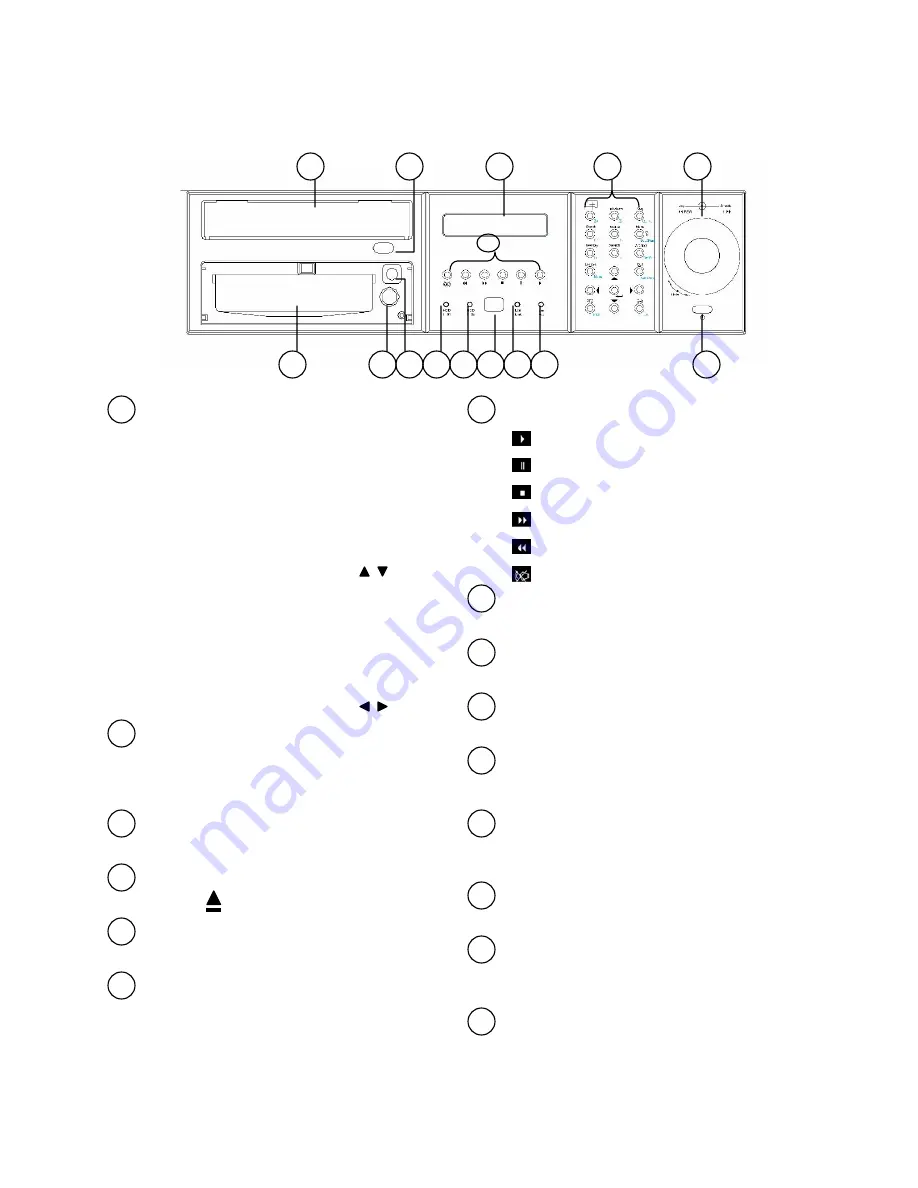
EverFocus eDR1680 Series Operating Instructions Manual Download Page 7

7

2. Part Names

2.1 Front Panel 

1

2

4

3

5

6

1

2

4

3

5

6

8

10

9

11

7

12

15

14

13

Jog Dial (inner) and Shuttle Ring (outer)

Jog Dial

A. Rotate in paused playback to move 

forward or backward to the next recorded 

image

B. In Setup Menu, rotate to select the 

options in the column (Same as         keys)

Shuttle Ring

A. Rotate in playback to search the 

recorded images in variable speed.

B. In Setup Menu, rotate to select the 

options in the column (Same as         keys)

Function Keys Panel

General Mode Panel(white) and PTZ Control 
Panel (Cyan). Please refer to Chapter 5 for 
detail function.

LCD Panel

To display the Date/Time, Recording status, etc.

Eject Button

Press to       eject CD-RW disc tray.

CD-RW

Built-in CD-RW.

Power Switch and Indicator

Press to turn On/Off the power.

7

Playback Buttons

Press to start playback

Press to pause playback

Press to stop playback    

Press to fast forward playback

Press to fast rewind playback

Press to mute status On/Off

8

LAN Active Indicator

Flashed when LAN is accessed.

9

10

LAN Link Indicator

Illuminates when LAN is connected.

IR Receiver

For IR Remote Controller (ERC100)

11

12

13

14

15

HDD I02 Indicator (Internal HDD)

Illuminates when HDD I02 (hot-swappable) 
is accessed.

HDD Tray Lock

Lock the tray to enable the HDD I02 application.

HDD I01 Indicator (Internal HDD)

Illuminates when HDD I01 (built-in) is 
accessed.

DVR ID Switch

Switch the controlled ID (DVR1~DVR4) for 
ERC100 controller. The default setting is DVR 1. 

HDD Tray

HDD I02 (hot-swappable) 

Summary of Contents for eDR1680 Series

Page 1: ...1 Administrator s Guide and Operating Instructions Real Time Digital Video Recorder eDR1680 Series V 1 0...

Page 2: ...power off and refer servicing to qualified service personnel Moisture may damage the appliance and also cause electric shock Do not use strong or abrasive detergents when cleaning the appliance body U...

Page 3: ...should be handled carefully Check to ensure that the following items are included 1 Digital Video Recorder unit 2 User s manual 3 Power Cord 4 HDD tray key and screws 5 Built in 160 GB HDD 6 RS232 RS...

Page 4: ...wash bowl kitchen sink or laundry tub in a wet basement near a swimming pool in an unprotected outdoor installation or any area which is classified as a wet location Servicing Do not attempt to servi...

Page 5: ...put Setup 23 6 4 4 System Network Setup 25 6 4 5 System Dial up Setup 27 6 4 6 System E Mail Setup 27 6 5 Display Setup 28 6 5 1 Display Main Monitor Sequence Setup 28 6 5 2 Display Call Monitor Seque...

Page 6: ...camera Alarm processor with configurable triggering conditions and reactions Alarm history log for Video Loss Motion Alarm input etc Pre record time up to 10 seconds Sophisticated PTZ control function...

Page 7: ...utton Press to eject CD RW disc tray CD RW Built in CD RW Power Switch and Indicator Press to turn On Off the power 7 Playback Buttons Press to start playback Press to pause playback Press to stop pla...

Page 8: ...witch to the correct position so that the number shown is the same as the local AC voltage Cooling Fan 9 SCSI Connector For connecting the optional extension unit Reserved Alarm Inputs Connect to alar...

Page 9: ...of the CD RW disc tray ID Buttons One Remote Controller can control up to 4 DVRs Press the buttons to switch the controlled ID DVR1 DVR4 The default setting is DVR 1 Function Buttons General Mode Pane...

Page 10: ...k Array Alarm In Alarm Out Ethernet Modem Main Monitor Y C Main Monitor CVBS Audio Out Main Monitor VGA Call Monitor Audio In 1 4 Camera In 1 8 Camera In 9 16 Basic Connection Cameras Connect each cam...

Page 11: ...Alarm Out 3 4 7 8 to NO type Microphone Speaker Connect the microphone speaker or other audio devices to the Audio In Audio out connector PTZ Camera Connect a PTZ camera to the RS 232 Com 2 connector...

Page 12: ...ay Status Menu Search Archive Event CH Set Del Exit PTZ Exit Auto Pan Set Pan Set Pr Seq Pr Go Pr Z Z F F I I PTZ Full Zoom Switch the focus window to full screen mode Press again to Digital Zoom in X...

Page 13: ...n the Shuttle to move between main menu and submenu For Left and Right Please refer details for menu setting in chapter 6 Live Play Press to select between Live Mode or Playback Mode for focus channel...

Page 14: ...otocol dome C1487M Kalatel Cyber Dome Philips Auto Dome Samsung SCC 641P SPD 2500 Subject to further notice if there is update support protocol Z Zoom In Z Zoom Out F Focus Far F Focus Near I Open IRI...

Page 15: ...e or JOG to move among the alphanumeric keys Press Enter button to confirm the selected character Move to key and press Del button can delete the wrong character inputted if necessary Use or Shuttle t...

Page 16: ...e It is not able to appear same camera in different windows in the same split display Sequence Display Mode Press SEQ button to toggle between Sequence and Static Display Mode Sequence can be displaye...

Page 17: ...r the submenu or return to upper level Press Enter button to close Setup Menu and enter the selected Configuration Dialog The shows on the item means a submenu is available for further configuration G...

Page 18: ...art Camera Calendar General Advanced Global Logout Password General Network Alarm Input Main Monitor Seq Call Monitor Seq Dial up E mail Alarm Action System Hard Disk Display Motion Detection Motion A...

Page 19: ...r items are settable if the selected camera is installed Default value is ON Tag Color 10 options select the desired camera tag color Blackout Select ON to enable blackout the corresponding camera The...

Page 20: ...of each time type please refer Chapter 7 Calendar setup menu Motion Select ON OFF to enable disable the Motion detection for corresponding camera Default value is ON While the ON option is selected t...

Page 21: ...onding Motion Action while motion detection is enabled Default value is MotionA01 Move the focus to the Config icon will be enabled for user to configure the motion action behavior Move the focus to t...

Page 22: ...is ON Log Log to event log list or not Please refer to Event Log for the details Default value is ON Show Message To display the alarm message or not when the Motion Action is triggered Default value...

Page 23: ...mera Default value is 10 Sec Alarm Output To define which Alarm Output will be triggered when there is video loss of corresponding camera Alarm Output 1 2 5 6 are NC type of signal Alarm Output 3 4 7...

Page 24: ...While the Timestamp is On user may define its Color and Position from the options shown on the screen Color 10 options select the desired time stamp color Default color is black Position 4 options Def...

Page 25: ...item and press Enter to pop up the Day Mode Setup Dialog Figure 2 to define the desired day type Default values are Work Day Holiday Special and Others Weekday Block Once you move to the weekday bloc...

Page 26: ...ter changed the language you need to reboot the machine to activate the setting Factory Setting Reset all configuration to factory setting All configuration set before will be ignored System Upgrade R...

Page 27: ...gered when HDDS are full and available space XX Default value is 10 Alarm Output N A 1 8 Default value is N A Buzzer ON OFF Default value is OFF Duration Duration time 00 99 seconds Default value is 1...

Page 28: ...the edit function Figure 2 to edit the alarm input total 10 characters available Move to OK icon after finished editing and press Enter button to confirm editing Press Exit button to return to previou...

Page 29: ...e NC type of signal Alarm Output 3 4 7 8 are No type Select N A to disable alarm output Default value is 1 alarm output 1 Buzzer To activate ON buzzer or not OFF while alarm is triggered Default value...

Page 30: ...vailable for the system Submask Enter the corresponding Subnet Mask Gateway For local network leave the column blank to disable gateway For Internet connection enter the reasonable gateway IP address...

Page 31: ...ed Dial In Users can dial in to the system for remote operation through the selected dial up method Enter the proper dial in details as required in the Dial in column Users may use the default Local I...

Page 32: ...the reasonable system e mail address The address will be shown on the notification mail as the sender s address Send Mail to The system can send e mail notification to up to 6 receivers for each actio...

Page 33: ...16 pages 4 Window 7pages 7 Windows 4 pages 9 Windows 3 pages 10 Windows 3 pages 13 Window 3 pages 16 Window 2 pages Dwell Time Select the Dwell Time 1 99 Sec for each selected page Default value is 5...

Page 34: ...up The Call Monitor Sequence Setup allows administrator to define the regular behavior of the call spot monitor Dwell Time 11 options OFF 1 2 3 5 10 15 20 30 45 60 seconds Each camera can set differen...

Page 35: ...ons or Jog to select the user level Name Password Confirm When the focus move to these items simulated keyboard will pop up automatically for character input Figure 2 Use buttons or Shuttle to select...

Page 36: ...t To logout the system press Enter button to invoke the Logout Dialog as shown in below The default setting for confirm dialog is No Use buttons or Shuttle to select the Yes to confirm then press Ente...

Page 37: ...set desired view windows or all windows in Playback mode Then press on the playback panel to start playback multi window video Press Live Play button to designated view window to return to live mode F...

Page 38: ...playback any time during playing back 3 Move the focus to Play icon then press Enter to start playback the video Note If the search time is not valid the Play icon will not be activated 7 2 1 Search b...

Page 39: ...to search by Smart Search 2 Select desired Camera The selected camera will show on the display window of the dialog 3 Select the desired Date Time 4 Select the Mask Type 3 options 4x3 8x6 16x12 5 Sele...

Page 40: ...t Archive first 2 Select desired Camera Cam1 Cam16 The selected video will show on the view window in the dialog 3 Select the media CD RW 4 Select the File Size 10 options Unlimited 1 4 5 10 20 50 100...

Page 41: ...e dialog 3 Move the focus to Load icon and press Enter button to load the video from the CD RW The loaded video list will appear on the left charter of the display 4 Move the focus to the desired list...

Page 42: ...Camera2 Motion 04 10 07 08 00 Camera3 Vloss 04 10 08 51 10 Camera4 Motion 04 10 10 22 37 Camera1 Motion 04 10 11 10 00 Camera2 Vloss 04 09 23 10 00 Camera1 Vloss Operation 1 Select Option 7 options Al...

Page 43: ...se IRIS GO Pr Goto Preset position The dialog will show on the focus camera Use to select the preset position 1 10 Seq Pr Sequence tour on preset position 1 10 The dialog will show on the focus camera...

Page 44: ...8 10 5 must be the same IP address as the one assigned to the unit from the Network Setting Menu The digital video recorder login page will show on the screen User must enter the correct user name and...

Page 45: ...n If any icon is grayed it means that the specific function is not accessible in the current mode The followings are a brief description for each of the icons STOP Stop recording 1 2 3 LIVE Show live...

Page 46: ...screen Sever split screen Nine split screen Sixteen split screen view OSD Enable On Screen Display text OSD Edit Edit On Screen Display text and text color Event Log Switch to Event Display mode Camer...

Page 47: ...Search Mode showing Event List Date Range and Play Back Panel 20 HDD Mode Display current Hard Drive storage status Event List List the Event History and time stamps Date Time Ask user to input Date...

Page 48: ...back the Video Step Forward the Video display Fast Forward fast forward the Video display PLAY PANNEL Play Panel Control Area PTZ Functions PTZ Panel to Preset sequentially presend camera Iris contro...

Page 49: ...quence Preset set up the display Sequence Iris Iris Control user can Increase or Decrease the IRIS setting by clicking or Auto Focus click check box to active Auto Focus Adjust Focus By clicking the o...

Page 50: ...e T LAN controller Chip RealTek 8019 LAN Connector RJ 45 Protocol HTTP TCP IP ICMP ARP Remote Access Standard browser such as internet Explorer Netscape with JAVA support Image Compression JPEG Used P...

Page 51: ...1 3 160 18 7 21 2 23 4 27 6 240 9 3 10 6 11 7 13 8 480 9 92 8 72 7 92 6 72 fps Level 3 Level 2 Level 1 Level 0 Speed PICTURE QUALITY KB Recording PAL 280 318 6 350 7 413 4 16 140 159 3 175 4 206 7 32...

Page 52: ...46 8 55 1 240 18 7 21 2 23 4 27 6 480 9 92 8 72 7 92 6 72 fps Level 3 Level 2 Level 1 Level 0 Speed PICTURE QUALITY KB Recording PAL 560 637 1 701 5 826 7 16 280 318 6 350 7 413 4 32 186 7 212 4 233...

Page 53: ...There are situations that the user will be asked to enter a numeric or alphanumeric string So a Simulated Keyboard is designed for the user to use the mouse for all the operations Please refer to the...

Page 54: ...t IP address Submask Gateway and DNS parameters Q I am not able to sent out email A Please make sure the machine is connect to the Internet and refer to chapter 6 for System Email Setup Q How to setup...

Page 55: ...lbert Einstein Strasse 1 D 46446 Emmerich Germany TEL 49 2822 9394 0 FAX 49 2822 939495 www everfocus de Japan Office 1809 WBG Maribu East 18F 2 6 Nakase Mihama ku Chiba city 261 7118 Japan TEL 81 43...

Reviews: