background image

3-9

E

3-8

MANU

If the IRIS item is set to MANU, the sub screen to open and shut the Iris
manually will be shown. Using the [Left, Right] keys in the LEVEL item
you can set Iris manual setting.

SHUTTER

In the SHUTTER menu, the high-speed Electric shutter and AUTO low speed
shutter of the ED2250S/P and the FIX low speed shutter can be set.
The High speed Electric Shutter supports 7 different speeds from 1/100 to
1/10K of a second. The AUTO low speed shutter and FIX low speed shutter
supports 12 different speeds from 2x to 128x magnifications.
The Low speed shutter is the function that sets the shutter speed to low in
order to clearly see the object filmed in low light.  To automatically slow down
the speed of the shutter by sensing the brightness of the light, set to AUTO
low speed shutter, and If the user wants to manually set the speed of low
speed shutter, set it to FIX. The number after the AUTO and FIX are the
number of the fields stored. The larger the number of the fields, the slower the
shutter speed gets, so in a still screen the screen is much clearer.
If the object were in motion it would be blurry.

Press

[Enter]

(VIDEO SET)

IRIS

MANU...

SHUTTER

AUTOx4

MOTION

NORMAL

WHITE BAL

ATW 

SPECIAL

OFF

AUTO FOCUS

ONEAF

D-ZOOM

OFF

EXIT

QUIT

(MANUAL)

LEVEL (  00)          ----

----

RET                      

(VIDEO SET)

IRIS

ALC...

SHUTTER                AUTOx4

MOTION

NORMAL

WHITE BAL

ATW 

SPECIAL

OFF

AUTO FOCUS

ONEAF

D-ZOOM

OFF

EXIT                         QUIT

ALC

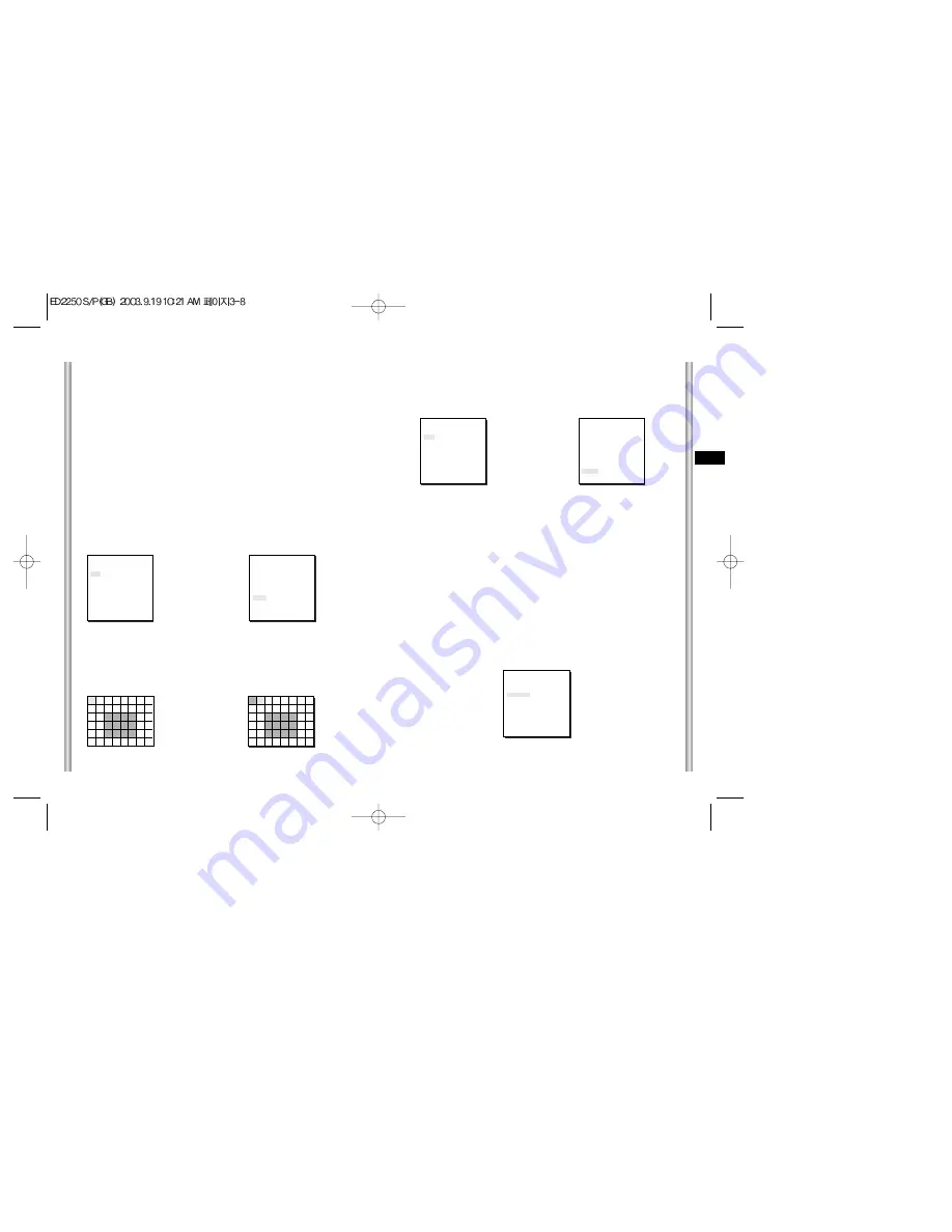
Choose the ALC of the IRIS item and press [ENTER] and set he submenu to
the Video Output level and BLC will be shown.The Video Output Level can
be set in the level item using the [Left, Right] keys.

BLC

(Submenu of the ALC menu)

With conventional cameras, strong background lighting interferes with the
clarity of objects, making them appear dark.  In the ED2250S/P, setting the
BLC (Back Light Compensation), submenu of ALC/MANU menu, will solve
the problem of backlight and give you a clear screen.
Set the BLC menu to ON and the Back Light Compensation function will be
applied to the screen areas of AREA menu.The screen area where Back
Light Compensation should be applied can be set with the PRESET or
USER item.If the AREA menu is set to PRESET, the backlight compensation
function is applied to the factory defaults of the ED2250S/P.
If the AREA menu is set to USER and [ENTER] is pressed, the user can
select the applied area of the backlight compensation function.

Use the [left, right, up, down] keys to move to the area you want.
Press the [5] key to assign an area or to cancel the area.
Press the [ENTER] key again to exit the “AREA” setup menu.

Press

[Enter]

Use the 

[Left, Right, Up, Down] Keys

(ALC)

AREA               PRESET...
BLC                  OFF
LEVEL (0)          ----

----

RET                      

(VIDEO SET)

IRIS

ALC...

SHUTTER

AUTO x 4

MOTION

NORMAL

WHITE BAL

ATW 

SPECIAL

OFF

AUTO FOCUS

ONEAF

D-ZOOM

OFF

EXIT

QUIT

Summary of Contents for ED2250S/P

Page 1: ...E D F Es I Part AB68 00411A Printed in Korea Combi Dome Camera ED2250S P Owner s Instructions Benutzerhandbuch Manuel d instruction Manual del usuario Istruzioni per l uso...

Page 2: ...may result in discoloration of surface or cause damage to the finish Caution 1 Do not drop objects on the product or apply strong shock to it Keep away from a location subject to excessive vibration...

Page 3: ...Usage This is a basic instruction manual for the ED2250S P user It contains all the instructions needed to use the ED2250S P from a simple introduction of the control locations and functions of the ED...

Page 4: ...on 2 4 Installing ED2250S P 2 5 Installing the Camera 2 8 Chapter 3 Setup Menu Overview 3 1 Structure of the Setup Menu 3 2 1 CAMERA SET MENU 3 4 CAMERA ID 3 4 V SYNC 3 4 COLOR BW 3 5 ZOOM SPEED 3 6 M...

Page 5: ...or rendition under any light conditions BLC function that enables effective back light compensation even under a spotlight or a very bright incident light Auto Focus function that automatically tracks...

Page 6: ...1 8 E 1 7 BACK Locations of Control FRONT ZOOM LENS COVER DOME COVER BODY...

Page 7: ...0 1 2 3 4 5 6 7 8 ON OFF BAUD RATE 4800 BPS 9600 BPS 19200 BPS 38400 BPS PIN 3 ON OFF ON OFF PIN 4 ON ON OFF OFF A EVER FOCUS ED2200Z PIN5 PIN6 PIN7 PIN8 A OFF OFF OFF OFF B ON OFF OFF OFF C OFF ON OF...

Page 8: ...ON ON ON ON ON ON OFF OFF OFF OFF OFF OFF OFF OFF OFF OFF OFF OFF OFF OFF OFF OFF ON ON ON ON ON ON ON ON SW500 6 OFF OFF OFF OFF OFF OFF OFF OFF OFF OFF OFF OFF OFF OFF OFF OFF OFF OFF OFF OFF OFF OF...

Page 9: ...N ON ON ON ON ON ON ON ON ON ON ON ON ON ON ON ON ON ON ON ON ON ON ON ON ON ON ON ON ON ON ON ON ON ON ON ON ON ON ON ON Receiver Address 56 57 58 59 60 61 62 63 64 65 66 67 68 69 70 71 72 73 74 75 7...

Page 10: ...OFF OFF OFF OFF OFF OFF ON ON ON ON ON ON ON ON OFF OFF OFF OFF OFF OFF OFF OFF ON ON ON ON SW500 5 ON ON ON ON ON ON ON ON ON ON ON ON ON ON ON ON OFF OFF OFF OFF OFF OFF OFF OFF OFF OFF OFF OFF OFF...

Page 11: ...anchor Camera Holder Cover Body Owner s Instructions Screws In this chapter we will check the contents of the package before installing the ED2250S P and prepare a power adapter suitable for the power...

Page 12: ...Adapter to the proper voltage Then connect the Power Adapter s plug to the Power Connector 5 Connect the Remote Control Terminal of the ED2250S P and the external Controller Controller Adapter BOARD T...

Page 13: ...pace above the ceiling board is over 18 cm 7 in high 3 Use the supplied screws to fasten the camera to the bracket assembly 4 Keep persons away from the installation area as there is a risk of falling...

Page 14: ...be installed The hole should be about 180 4 Figure 3 4 Connect the various cables to the CAMERA ADAPTER See page 2 4 Figure 4 Figure 3 Installing the Camera Figure 1 Length of ceiling Hole 5 CEILING M...

Page 15: ...tch the 3 holes on the back of the CAMERA and the CONNECTOR and turn it left about 15 degrees Check the sound of LOCKING and that the LEVER LOCKING is in place Use the screws BH M3 x L8 to connect the...

Page 16: ...3 HALF1 HALF2 FULL ALARM3 OFF 1 3 HALF1 HALF2 FULL ALARM4 OFF 1 3 HALF1 HALF2 FULL MOTION OFF 1 3 HALF1 HALF2 FULL EXIT QUIT SAVE AUX OUT CONTROL OUT1 ON OFF OUT2 ON OFF OUT3 ON OFF EXIT QUIT SAVE OTH...

Page 17: ...t the brightness level that changes from the COLOR Mode to BW Mode in 3 steps LOW MEDIUM and HIGH CAMERA SET CAMERA ID OFF V SYNC INT COLOR BW AUTO ZOOM SPEED 3 MOTION DET OFF EXIT QUIT COLOR The IR F...

Page 18: ...y and the Area of Motion Detection If the Motion Detection function is set the movement of an intruder can be detected When motion is detected it sets off the Alarm signal of the Controller If you sel...

Page 19: ...00 I RET VIDEO SET IRIS ALC SHUTTER AUTOx4 MOTION NORMAL WHITE BAL ATW SPECIAL OFF AUTO FOCUS ONEAF D ZOOM OFF EXIT QUIT ALC Choose the ALC of the IRIS item and press ENTER and set he submenu to the V...

Page 20: ...1 100 1 120 1 250 1 500 1 1000 1 2000 1 4000 1 10K OFF AUTOX2 AUTOX4 AUTOX6 AUTOX8 AUTOX12 AUTOX16 AUTOX24 AUTOX32 AUTOX48 AUTOX64 AUTOX96 AUTOX128 OFF FIX X2 FIX X4 FIX X6 FIX X8 FIX X12 FIX X16 FIX...

Page 21: ...emperature to 3200 K 5600 K Set color temperature to 5600 K User Set the appropriate value in the RED and BULE graph MANU Select MANU item and press ENTER the sub screen where you can select Manual Wh...

Page 22: ...O FOCUS ONEAF D ZOOM X10 EXIT QUIT VIDEO SET IRIS ALC SHUTTER AUTOx4 MOTION NORMAL WHITE BAL ATW SPECIAL OFF AUTO FOCUS ONEAF D ZOOM OFF EXIT QUIT VIDEO SET IRIS ALC SHUTTER AUTOx4 MOTION NORMAL WHITE...

Page 23: ...o saves the selected information and returns to a higher menu DEL Deletes the selected information and restores the DEFAULT Then returns to a higher menu PRESET NO 0 SET PAN TILT SET ZOOM FOCUS PRESET...

Page 24: ...Press Enter MAIN MENU CAMERA VIDEO SET PRESET AUTO MODE ALARM SET OTHER SET SCAN MODE AUTO PAN PATTERN SET 1 RET SET END END SET From END SET get into the END SET setup screen by pressing ENTER Adjust...

Page 25: ...as an ALARM signal when it continues more than 150ms for a time and each ALARM movement time is decided depending on it s correspondence to the DWELL TIME of the PRESET and PATTERN connected ALARM PR...

Page 26: ...ter KEY The PAN TILT Setup is Complete PRIVACY ZONE SET 1 SET PAN TILT SET AREA SET LEVEL 1 EXIT QUIT PRIVACY ZONE SET 1 SET PAN TILT SET SET AREA SET LEVEL 1 EXIT QUIT 6 OTHER SET HOME RETURN When th...

Page 27: ...Mode Resolution S N Ratio Min Object Illumination Color Temperature Signal Output Lens PAN Function TILT Function REMOTE CONTROL ALARM Operation Temperature Operation Humidity SIZE Weight ED2250S P 3...

Page 28: ...anual belongs to Samsung Electronics Co Ltd Without the permission of Samsung Electronics it cannot be reproduced electronically mechanically audibly or by any other method This manual will be modifie...

Reviews: