background image


- 20 - 


5.5. Adjustment of the rotation device 

Pressure Port(RA)
(Counter-clockwise Rotation)

Pressure Port(RB)
(Clockwise Rotation)

Pressure Relief Valve

for Motor

Built-in Relief Valve

(Look from direction A,B)

(A VIEW)

B

(B VIEW)

Stop Valve of

Main Line

Stop Valve of

Rotation Line

A


Figure 15 

A built-in relief valve, in which a relief valve to protect rotation motor is built in EVERDIGM hydraulic grab 
EPG-series. Do not reset this relief valve because it is set in the factory when delivery. If reset is required, 
follow the instructions below. 

A built-in relief valve will be seen as Figure 15.


Setting of the relief valve :


  Port for pressure check is positioned in both ports 

„RA‟ and „RB‟. Place a pressure gauge into either port, 

and set the minimum pressure unscrewing the pressure relief valve to the end. The pressure gauge must 
be for 400 bar or more. 

  Place the grab to the ground or the other strong structure so that the grab can not rotate. 

  Increase  pressure  by  screwing  the  screw  adjuster  until  the  pointer  of  the  pressure  gauge  reaches  the 

recommended pressure  with the rotation actuator of the carrier switched on.  Recommended pressure is 
less than 100 bar. 

  Pay attention to the max pressure since motor life will be reduced if it is used over maximum pressure. 


DANGER! 

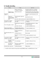
Pay attention to the safety in case a worker is vicinity of working area. Never operate the grab 
with workers in close proximity to the grab. 


IMPORTANT! 

Do not reset the relief valve if possible. The rotation motor life will reduce if the pressure is set 
exceeding the allowed pressure. 


Summary of Contents for EPG05

Page 1: ...OPERATION MAINTENANCE MANUAL Multi Purpose Grab Document No MSAGUS 0005 Revision Date 2014 09 23...

Page 2: ...may be changed If you found the parts unclear or not corresponding to the grab call and consult EVERDIGM dealer or service center Important information on safety is described in the safety information...

Page 3: ...3 Technical specifications 12 4 Markings and labels 13 5 Installation 15 5 1 Lifting the grab 15 5 2 Requirements on the carrier 15 5 3 Installation of hydraulic piping on the carrier 17 5 4 Mounting...

Page 4: ...ever fail to read and observe the instructions for safe operation Signal Words The words DANGER WARNING CAUTION and IMPORTANT appeared with the above Safety Alert Symbol indicate degree of risk of haz...

Page 5: ...ly and is placed stably in the safe place Figure 1 Know your equipments Never fail to read and understand the safety messages operation manual and maintenance manual before installation and operation...

Page 6: ...ents falling down when the grab is working on the tall columns supports and brick the carrier should be equipped with the cab protector strong enough for the falling elements For more information on t...

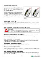
Page 7: ...or operating the grab WARNING The following instructions are on safety in operation with grab Read understand and observe the instructions More information is provided in page 23 6 3 Operation Never o...

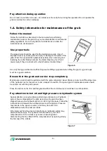
Page 8: ...ood condition Ensure that the grab and carrier stop completely Maintenance work should be performed with the grab completely closed Make sure to shut off the stop valve of the hydraulic line for the g...

Page 9: ...may be slippery The oil wet on the ground may be very slippery Collect any oil and dispose it correctly Do not alter or modify Unauthorized alteration or modification of the grab shall not be guarante...

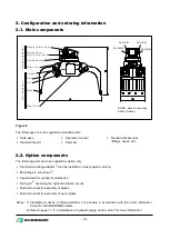
Page 10: ...ndard accessories fittings hoses etc 2 2 Option components The following parts are to be supplied as option only Standard mounting adapter 1 can be installed on most popular carriers Mounting pin bush...

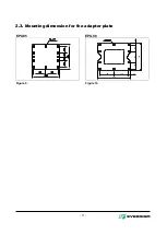
Page 11: ...11 2 3 Mounting dimension for the adapter plate EPG05 EPG08 Figure 9 190 190 430 400 160 100 100 25 20 Figure 10...

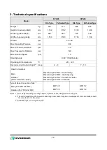
Page 12: ...erating Oil Temperature C 20 90 Recommended Carrier Weight 2 tonne 4 8 7 10 Hose Connections Main Pressurizing Port MA Grab Closing Pressurizing Port MB Grab Opening Rotation at the view from carrier...

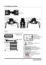
Page 13: ...Pay attention to the marks and labels related to safety EVERDIGM Logo CE Label Stay Clear Indicates that the distance must be kept to be safe from the flying rock splinter Lifting Point Indicates the...

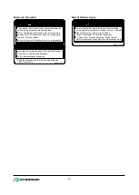
Page 14: ...he manuals prior to initial use and follow the Do not operate when bystanders are in working area cab using the necessary window guarding The operator must be adequately protected within the Risk of S...

Page 15: ...and low crushing force respectively Check the specification of the carrier For the hydraulic grab the inner diameter of the hydraulic line must be correspond to page 12 3 Technical specifications or b...

Page 16: ...to grab piping lines take the return line of the existing breaker piping lines for the grab closing lines of the grab If the return line of the existing breaker lines is also installed for low pressu...

Page 17: ...maximum pressure in grab opening and closing operation Flow control valves to adjust working speed and rotation speed but it is necessary not to exceed recommended speeds otherwise hydraulic motor and...

Page 18: ...ke care of the direction of the mounting adapter as the drawing Set the carrier s engine speed to low idle and move the stick of carrier slowly until its hole is aligned with that in the mounting adap...

Page 19: ...injury Match the holes by only visual lining up While moving the carrier make sure that there is no person in the vicinity of the carrier Personal injury can result also from dropping the mounting pin...

Page 20: ...RB Place a pressure gauge into either port and set the minimum pressure unscrewing the pressure relief valve to the end The pressure gauge must be for 400 bar or more Place the grab to the ground or t...

Page 21: ...ow control valve in the carrier s rotation pipe The proper rotation speed is 7 12 rpm and it must not exceed 15 rpm IMPORTANT It will cause personal injury damage to the grab or inconvenience operatio...

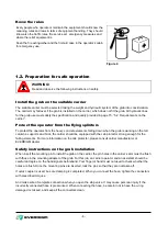
Page 22: ...ng of the grab no abnormal sound and no vibration during the operation WARNING Read carefully and follow all safety regulations concerned with the preparation for safe operation Refer to page 6 1 2 Pr...

Page 23: ...please stop the carrier and wait until the oil has cooled to operating temperature range For continuous operation with high duty maximum oil temperature is recommended not to exceed 80 C 175 F An auxi...

Page 24: ...ry or death Never operate the grab unless you are properly trained DANGER Figure 17 DO CRUSHING FROM THE TOP DOWNWARDS Always be careful of falling down of broken elements When crushing columns chimne...

Page 25: ...a where high pressure piping or similar gas piping was laid out High pressure gas piping can be explosive at damage WARNING IMPORTANT Figure 21 DO NOT USE FOR TRANSPORT PURPOSES The hydraulic grab is...

Page 26: ...IMPORTANT Figure 24 DO NOT SUPPORT THE CARRIER WITH THE GRAB Never support the carrier s weight with the grab i e jack up with grab to rotate the carrier s undercarriage This will cause serious damage...

Page 27: ...igure 28 DO NOT ROTATE THE GRAB WHILE CRUSHING IS IN PROGRESS This will cause damage to the grab and carrier s arm IMPORTANT NEVER ATTEMPT TO DO UNALLOWED JOB Do not attempt to do job other than open...

Page 28: ...28 Please consult EVERDIGM dealer for the operation in special applications such as underwater use cutting high temperature object bitting off ladle slag in iron works...

Page 29: ...grab visual inspection Check whenever inspecting if there are oil leaks at the hydraulic components or the hydraulic connections of the grab Check whenever inspecting if all fasteners such as bolts nu...

Page 30: ...if there is a crack in the welded part of the grab Check the hydraulic components of the carrier Check abnormal sound or vibration during the grab movements and rotation of the grab Every 1000 hours o...

Page 31: ...7 Hex head 7 8 M10 x 1 5 8 Hex socket 7 8 M12 x 1 75 19 Hex head 12 14 M12 x 1 75 10 Hex socket 12 14 M14 x 2 22 Hex head 19 21 M14 x 2 12 Hex socket 19 21 M16 x 2 24 Hex head 30 33 M16 x 2 14 Hex soc...

Page 32: ...used Using the oil with higher viscosity too thick may cause Generating shock while cylinder is in operation Risk of failure in the pumps and rotation motor Life time of hydraulic oil filter shortene...

Page 33: ...s Oil filters Every 100 hours Oil cooling The maximum permitted hydraulic oil temperature in continuous grab operation is 90 C 194 F Therefore a reliable hydraulic oil thermometer is necessary If ther...

Page 34: ...open Take care of the safety against the grab after dismounting so that it can t fall over After turn stop valves to OFF position disconnect hydraulic hoses from the stop valves Apply end caps and plu...

Page 35: ...rect operating pressure or contact EVERDIGM service Defective relief valve Contact EVERDIGM service Grab can not rotated or abnormal noise during rotation Hydraulic motor pinion or slewing bearing are...

Page 36: ...36 Notes...

Page 37: ...37 Notes...

Page 38: ...on s Valley 680 Gasan Dong Geumcheon Gu Seoul Korea 153 803 Tel 82 2 801 0800 Fax 82 2 801 0899 Head Office 332 3 Janggwan ri Jincheon eub Jincheon gun Factory Chungcheongbuk do Korea 365 802 Tel 82 4...

Reviews:

Related manuals for EPG05