EVCO S.p.A.
c-pro 3 micro and c-pro 3 kilo | Hardware manual ver. 1.1 | Code 114CP3UKE114
page 1 of 62
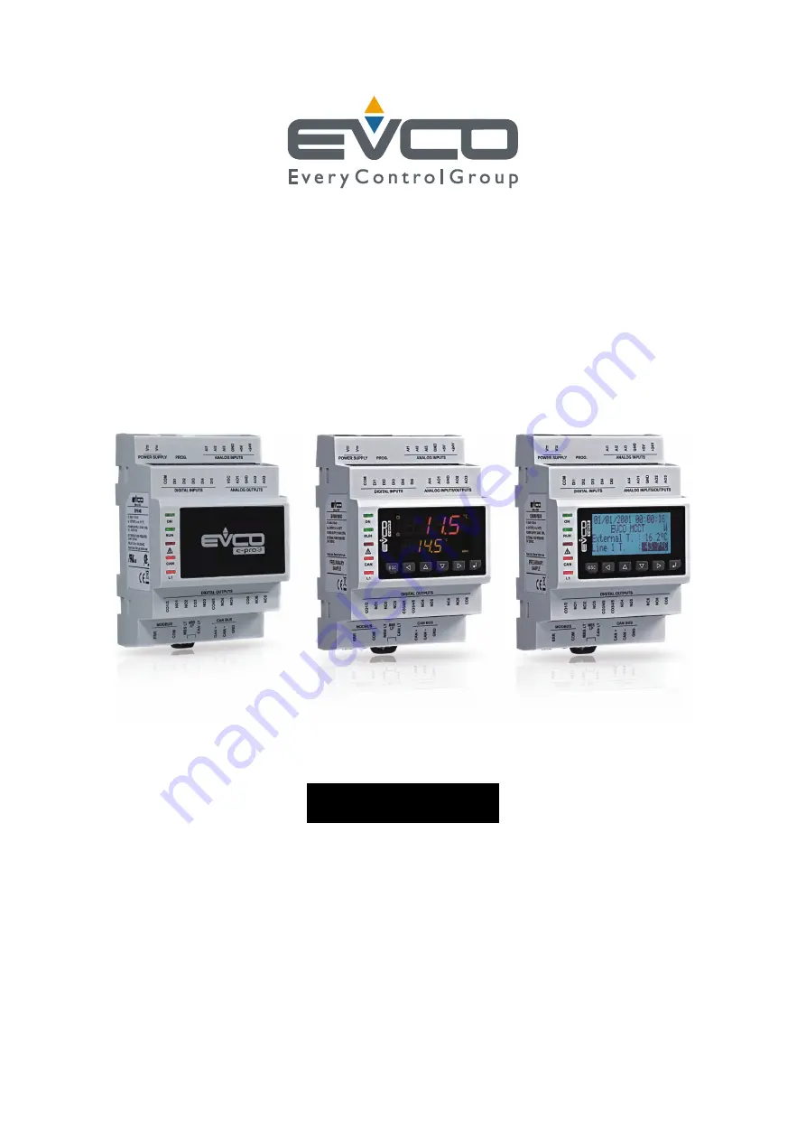
c-pro 3 micro and c-pro 3 kilo
PROGRAMMABLE CONTROLLERS
ENGLISH
HARDWARE MANUAL ver. 1.1
CODE 114CP3UKE114
Page 1: ...EVCO S p A c pro 3 micro and c pro 3 kilo Hardware manual ver 1 1 Code 114CP3UKE114 page 1 of 62 c pro 3 micro and c pro 3 kilo PROGRAMMABLE CONTROLLERS ENGLISH HARDWARE MANUAL ver 1 1 CODE 114CP3UKE114 ...
Page 2: ...e structure The new UNI PRO version allows backward compatibility with the devices previously manufactured and or delivered while binary projects or applications precompiled with UNI PRO versions older than the 3 20 0 0 will need to be recompiled if used with devices featuring the new hardware structure The devices requiring updating are identified in the product label with 2 letters inside the nu...
Page 3: ...e additional information for the installation and for the electrical connection keep this document close to the devices for future consultations The following symbols support the reading of the document it indicates a suggestion it indicates an additional information to be followed The devices must be disposed according to the local legislation about the collection for electrical and electronic eq...
Page 4: ...vice 25 6 CONFIGURATION 27 6 1 Configuring a programmable controller 27 6 1 1 Configuring a built in programmable controller 27 6 1 2 Configuring a blind programmable controller 29 6 2 Configuring an I O expansion 30 6 3 Configuring a device through an user interface Vgraph Vtouch Vroom or Vcolor 31 6 4 List of configuration parameters 32 7 USER INTERFACES 46 7 1 Preliminary information 46 7 2 Vgr...
Page 5: ... x 64 pixel single colour LCD graphic display black with rearlighting through white LEDs and with a 6 buttons with preset functions keyboard made of silicone rubber integrated in the controller hereinafter also called built in LCD versions with 4 4 digits custom LED display with function icons and with a 6 buttons with preset functions keyboard made of silicone rubber integrated in the controller ...
Page 6: ...c pro 3 micro and c pro 3 kilo only unipolar stepper electronic expansion valves driver available in models c pro 3 micro and c pro 3 kilo only 4 display and keyboard not available in the blind versions 5 analog inputs 7 9 digital inputs 6 9 and analog outputs 4 6 available in models c pro 3 micro and c pro 3 kilo only 6 analog inputs 1 6 digital inputs 1 5 and analog outputs 1 3 7 OTG USB port 8 ...
Page 7: ... 3 kilo only 11 micro switch to plug in the termination of the RS 485 port with Modbus master communication protocol available in models c pro 3 micro and c pro 3 kilo only 12 signalling LEDs 13 according to the model digital outputs 8 available in models c pro 3 micro and c pro 3 kilo only unipolar stepper electronic expansion valves driver available in models c pro 3 micro and c pro 3 kilo only ...
Page 8: ...digital outputs 1 and 5 3 digital outputs 9 available in models c pro 3 EXP micro and c pro 3 EXP kilo only 4 analog inputs 7 9 digital inputs 6 9 and analog outputs 4 6 available in models c pro 3 EXP micro and c pro 3 EXP kilo only 5 analog inputs 1 6 digital inputs 1 5 and analog outputs 1 3 6 OTG USB port 7 micro switch to plug in the termination of the CAN port 8 power supply and CAN port 9 s...
Page 9: ... 3 micro and c pro 3 kilo Hardware manual ver 1 0 Code 114CP3UKE104 page 9 of 62 3 SIZE AND INSTALLATION 3 1 Size programmable controllers 4 DIN modules size in mm in 3 2 Size I O expansions 4 DIN modules size in mm in ...
Page 10: ...evices again press the DIN rail clips to the end first 3 4 Additional information for installation working conditions working temperature humidity etc must be between the limits indicated in the technical data do not install the devices close to heating sources heaters hot air ducts etc equipments provided with big magnetos big speakers etc locations subject to direct sunlight rain humidity dust m...
Page 11: ...E104 page 11 of 62 4 ELECTRICAL CONNECTION 4 1 Connectors programmable controllers The following drawing shows the connectors of c pro 3 micro and of c pro 3 kilo The following drawing shows the connectors of c pro 3 micro and of c pro 3 kilo Models with 9 electromechanical relays ...
Page 12: ...3 micro and c pro 3 kilo Hardware manual ver 1 0 Code 114CP3UKE104 page 12 of 62 Models with 7 electromechanical relays and 2 solid state relays Models with integrated unipolar stepper electronic expansion valves driver ...
Page 13: ... 114CP3UKE104 page 13 of 62 4 2 Connectors I O expansions The following drawing shows the connectors of c pro 3 EXP micro and of c pro 3 EXP kilo The following drawing shows the connectors of c pro 3 EXP micro and of c pro 3 EXP kilo Models with 9 electromechanical relays ...
Page 14: ...EVCO S p A c pro 3 micro and c pro 3 kilo Hardware manual ver 1 0 Code 114CP3UKE104 page 14 of 62 Models with 7 electromechanical relays and 2 solid state relays ...
Page 15: ... 3 res A 250 VAC CO1 2 common digital outputs 1 and 2 NO3 normally open contact digital output 3 3 res A 250 VAC NO4 normally open contact digital output 4 3 res A 250 VAC NO5 normally open contact digital output 5 3 res A 250 VAC CO3 4 5 common digital outputs 3 4 and 5 The maximum length of the connecting cables of the digital outputs is 100 m 328 ft Digital outputs 8 and 9 According to the mode...
Page 16: ...t in case of electromechanical relay 100 m 328 ft in case of solid state relay Unipolar stepper electronic expansion valves driver The following drawing shows the connectors of the unipolar stepper electronic expansion valves driver The following table shows the meaning of the connectors Terminal Meaning SOA unipolar stepper motor coli 1 SOB unipolar stepper motor coli 2 SOC unipolar stepper motor...
Page 17: ...g a twisted pair The following table shows the function codes supported by the controller Function code Meaning FC 01 read coils FC 02 read discrete inputs FC 03 read multiple registers FC 04 read input registers FC 05 write single coil FC 06 write single register FC 08 diagnostic FC 15 write multiple coils FC 16 write multiple registers FC 23 read write multiple registers For the settings about t...
Page 18: ...ration parameter for PTC NTC Pt 1000 probes 0 20 mA 4 20 mA 0 5 V ratiometric 0 10 V transducers AO4 analog output 4 configurable via configuration parameter for 0 20 mA 4 20 mA 0 10 V signal AO5 analog output 5 for 0 10 V signal AO6 analog output 6 for 0 10 V signal DI6 digital input 6 optoisolated 24 VAC DC and 50 60 Hz DI7 digital input 7 optoisolated 24 VAC DC and 50 60 Hz DI8 digital input 8 ...
Page 19: ...specifications and implementation guides manual the document is available on the internet site www modbus org The maximum length of the connecting cables of the CAN port depends on the baud rate of the CANbus communication as follows 1 000 m 3 280 ft with baud rate 20 000 baud 500 m 1 640 ft with baud rate 50 000 baud 250 m 820 ft with baud rate 125 000 baud 50 m 164 ft with baud rate 500 000 baud...
Page 20: ...he CANbus communication and on the kind of device in the network For example a CAN network can be made of a programmable controller of four I O expansions and of four user interfaces with baud rate 500 000 baud Connect the CAN port using a twisted pair For the settings about the CAN port look at chapter 6 CONFIGURATION Termination RS 485 port and termination CAN port Micro switch to plug in the te...
Page 21: ...g input 5 configurable via configuration parameter for PTC NTC Pt 1000 probes AI6 analog input 6 configurable via configuration parameter for PTC NTC Pt 1000 probes DI4 digital input 4 optoisolated 24 VAC DC and up to 2 KHz DI5 digital input 5 optoisolated 24 VAC DC and 50 60 Hz COM common digital inputs 12V power supply 0 20 mA 4 20 mA 0 10 V transducers 12 VDC 120 mA max 5VS power supply 0 5 V r...
Page 22: ... the connecting cables is 100 m 328 ft for the analog inputs 100 m 328 ft for the power supply of the transducers 100 m 328 ft for the digital inputs 1 m 3 280 ft for the PWM analog outputs 100 m 328 ft for the 0 20 mA 4 20 ma 0 10 V analog outputs For the settings about the analog inputs look at chapter 6 CONFIGURATION ...
Page 23: ... 23 of 62 4 3 1 Example of electrical connection The following drawing shows an example of electrical connection of c pro 3 kilo with c pro 3 EXP kilo and with Vgraph For the devices powered at 12 VAC the power supply of the devices in the network must be galvanically isolated one another ...
Page 24: ...e first and of the last element of the network 4 4 Additional information for electrical connection do not operate on the terminal blocks with electrical or pneumatic screwers if the device has been moved from a cold location to a warm one the humidity could condense on the inside wait about an hour before powering it test the working power supply voltage working electrical frequency and working e...
Page 25: ...e will be compiled and running in release modality if it flashes slowly the application software will be compiled and running in debug modality condition not allowed in c pro 3 EXP micro micro and in in c pro 3 EXP kilo kilo if it flashes quickly the application software will be compiled running in debug modality and stopped in a breakpoint condition not allowed in c pro 3 EXP micro micro and in i...
Page 26: ...ll not have been set up if it flashes slowly the CANbus communication will have been set up but it will not be completely correct if it flashes quickly the CANbus communication will have been set up and will be correct if it is out no CANbus communication will be running L1 LED auxiliary not used in c pro 3 EXP micro micro and in in c pro 3 EXP kilo kilo The operation of this LED can be programmed...
Page 27: ...o the Password submenu and to the Backup Restore submenu operate as follows 5 From step 2 press and release button UP or button DOWN to select the submenu 6 Press and release button ENTER 7 Press and release button ENTER again to set the password value 8 Press and release button DOWN over and over again to set 19 9 Press and release button ENTER again To modify a parameter operate as follows 10 Fr...
Page 28: ...ripheral this operation usually takes a few seconds if an error had to arise the LED system alarm look at paragraph 5 2 1 LEDs at the fron of the device will light up and parameter Key Par it belongs to the Diagnostic submenu will assume value Err 30 Disconnect the programming key To copy the parameters from an USB peripheral to the controller operate as follows 31 Make sure the power supply is sw...
Page 29: ...menu CPro 3 Kilo LCD Info English Parameters Backup Restore Diagnostic Debug 5 Press and release button UP or button DOWN to select Networks 6 Press and release button ENTER 7 Press and release button ENTER again to set the password value 8 Press and release button DOWN over and over again to set 19 9 Press and release button ENTER again 10 Press and release button UP or button DOWN to select CAN ...
Page 30: ...ing menu CPro 3 Kilo LCD Info English Parameters Backup Restore Diagnostic Debug 5 Press and release button UP or button DOWN to select Networks 6 Press and release button ENTER 7 Press and release button ENTER again to set the password value 8 Press and release button DOWN over and over again to set 19 9 Press and release button ENTER again 10 Press and release button UP or button DOWN to select ...
Page 31: ... CAN Network 7 Press and release button ENTER 8 Press and release button ENTER again to set the password value 9 Press and release button DOWN over and over again to set 19 10 Press and release button ENTER again 11 Set parameter NW Node using button UP or button DOWN to select the parameter and using button ENTER to modify and to confirm the value According to the factory setting the address of t...
Page 32: ...eter available in read only modality information about UNI PRO 3 version and revision Info SN parameter available in read only modality information about the serial number and the result of the productive test Info MASK parameter available in read only modality information about the mask it depends on the builder s coding system Info date and time parameter available in read only modality date and...
Page 33: ...alog input 3 PTC PTC probe NTC NTC probe 0 20mA 0 20 mA transducer 4 20mA 4 20 mA transducer 0 5V 0 5 V ratiometric transducer 0 10V 0 10 V ratiometric transducer PT1000 Pt 1000 probe NTCK2 NTC probe type 2 NTCK3 NTC probe type 3 RESIST reading of the electric resistance Parameters 1 AI4 NTC kind of probe analog input 4 PTC PTC probe NTC NTC probe PT1000 Pt 1000 probe NTCK2 NTC probe type 2 NTCK3 ...
Page 34: ... NTCK2 NTC probe type 2 NTCK3 NTC probe type 3 RESIST reading of the electric resistance Parameters 1 AI8 NTC kind of probe analog input 8 PTC PTC probe NTC NTC probe 0 20mA 0 20 mA transducer 4 20mA 4 20 mA transducer 0 5V 0 5 V ratiometric transducer 0 10V 0 10 V ratiometric transducer PT1000 Pt 1000 probe NTCK2 NTC probe type 2 NTCK3 NTC probe type 3 RESIST reading of the electric resistance Pa...
Page 35: ... 10 0 displacement of the cut phase pulse of the analog output 1 Parameters 1 AO2 0 10V kind of signal analog input 2 FAN FAN for cut phase module 0 10V 0 10 V PWM PWM Pulse With Modulation Parameters 1 freq 10 2000 Hz 1000 frequency of the PWM signal of the analog output 2 Parameters 1 Delay ph 0 50 ms 10 0 displacement of the cut phase pulse of the analog output 2 Parameters 1 AO3 0 10V kind of ...
Page 36: ...ntroller is disabled Parameters 2 press button RIGHT to show it En Prg Level NO enabling the access to the first level page pressing a combination of buttons YES yes operating as follows keep pressed 3 s button ENTER to gain access to the first page of level 1 keep pressed 3 s buttons ENTER and ESC to gain access to the first page of level 2 keep pressed 3 s buttons LEFT and RIGHT to gain access t...
Page 37: ...t not available in the built in LED versions and in the blind versions B Time 0 60 s 240 backlight duration only if parameter Backlight has value TIME Parameters 2 press button RIGHT to show it not available in the built in LED versions and in the blind versions Contrast 0 100 50 display contrast Parameters 2 press button RIGHT to show it not available in the built in LED versions and in the blind...
Page 38: ... and in the blind versions Time Char Sep time separator ASCII character Parameters 2 press button RIGHT to show it not available in the built in LED versions and in the blind versions Time With Sec YES showing the seconds in the real time YES yes Parameters 2 press button RIGHT to show it not available in the built in LED versions and in the blind versions Time AM PM NO time format NO 24 h for exa...
Page 39: ...k Networks CAN Bus NetworkNode 1 0 32 127 1 99 address of a remote or of a device in the network CAN node example for 1 2 1 node 2 node s address Networks CAN Bus press button RIGHT to show it TSEG1 0 15 10 reserved Networks CAN Bus press button RIGHT to show it TSEG2 1 7 2 reserved Networks CAN Bus press button RIGHT to show it SJW 0 3 0 reserved Networks CAN Bus press button RIGHT to show it BTR...
Page 40: ... it Cnt Tx parameter available in read only modality number of packages transmitted Networks CAN Bus press button RIGHT to show it Cnt Ovf parameter available in read only modality number of packages in overflow Networks CAN Bus press button RIGHT to show it Cnt Passive parameter available in read only modality number of transactions in passive status Networks CAN Bus press button RIGHT to show it...
Page 41: ...ion protocol NONE no parity ODD odd EVEN even Networks UART1 1 Stop 1 BIT Modbus communication stop bit number in a RS 485 network wired on the RS 485 port with Modbus slave communication protocol 1 BIT 1 bit 2 BIT 2 bit Networks UART1 1 Timeout 2 240 s 10 Modbus communication time out in a RS 485 network wired on the RS 485 port with Modbus slave communication protocol for the test of the remote ...
Page 42: ... communication stop bit number in a RS 485 network wired on the RS 485 port with Modbus master communication protocol 1 BIT 1 bit 2 BIT 2 bit Networks UART2 2 Timeout 2 240 s 10 Modbus communication time out in a RS 485 network wired on the RS 485 port with Modbus master communication protocol for the test of the remote values of the I O after this time without Modbus communication the request is ...
Page 43: ...o gain access to level 4 ON enabling the password to gain access to level 4 OFF to gain access to level 4 one has not to set any password ON to gain access to level 4 one has to set a password Password Level 5 32768 32767 0 value of the password to gain access to level 5 ON enabling the password to gain access to level 5 OFF to gain access to level 5 one has not to set any password ON to gain acce...
Page 44: ...eter available in read only modality Math status ok not in error err in error because of overflow underflow division by zero or NaN Diagnostic Key Par parameter available in read only modality result of the copy of the parameters from the controller to the USB peripheral ok operation successful completed err operazione failed Debug Algo Main time parameter available in read only modality main cycl...
Page 45: ... Debug 12V exp parameter available in read only modality reading the power supply voltage coming from the upper board Notes 1 the submenu is visible on condition that the application software expects the RS 485 port with Modbus slave communication protocol is configured to support the Modbus communication protocol 2 the submenu is visible on condition that the application software expects the RS 4...
Page 46: ... electrical panels and as well as in all those applications where a frontal protection degree IP65 is required built in by wall in traditional box like 506 by BTicino by wall on the support CPVW00 by EVCO to order separately Also the necessity to customize the interface in order to integrate it aesthetically in residential and commercial environments is satisfied by Vgraph since at the front of th...
Page 47: ...ware manual ver 1 0 Code 114CP3UKE104 page 47 of 62 7 2 3 Size Size in mm in Size Minimum Typical Maximum A 104 0 4 094 104 0 4 094 104 8 4 125 B 70 0 2 755 70 0 2 755 70 8 2 787 C 22 0 0 866 23 0 0 905 24 0 0 944 D 40 8 1 606 41 8 1 645 42 8 1 685 ...
Page 48: ...gree IP65 is required built in by wall in traditional box like 506 by BTicino by wall on the support CPVW00 by EVCO to order separately Also the necessity to customize the interface in order to integrate it aesthetically in residential and commercial environments is satisfied by Vtouch since at the front of the interface one can apply both the plates CPVP by EVCO to order separately made in plasti...
Page 49: ...re manual ver 1 0 Code 114CP3UKE104 page 49 of 62 7 3 3 Size Size is in mm in Size Minimum Typical Maximum A 104 0 4 094 104 0 4 094 104 8 4 125 B 70 0 2 755 70 0 2 755 70 8 2 787 C 22 0 0 866 23 0 0 905 24 0 0 944 D 40 8 1 606 41 8 1 645 42 8 1 685 ...
Page 50: ...box like 506 by BTicino by wall on the support CPVW00 by EVCO to order separately Also the necessity to customize the interface in order to integrate it aesthetically in residential and commercial environments is satisfied by Vroom since at the front of the interface one can apply both the plates CPVP by EVCO to order separately made in plastic material and available in two different colorations w...
Page 51: ...ware manual ver 1 0 Code 114CP3UKE104 page 51 of 62 7 4 3 Size Size in mm in Size Minimum Typical Maximum A 104 0 4 094 104 0 4 094 104 8 4 125 B 70 0 2 755 70 0 2 755 70 8 2 787 C 22 0 0 866 23 0 0 905 24 0 0 944 D 40 8 1 606 41 8 1 645 42 8 1 685 ...
Page 52: ...e 506 by BTicino by wall on the support CPVW00 by EVCO to order separately Also the necessity to customize the interface in order to integrate it aesthetically in residential and commercial environments is satisfied by Vcolor since at the front of the interface one can apply both the plates CPVP by EVCO to order separately made in plastic material and available in two different colorations white a...
Page 53: ...re manual ver 1 0 Code 114CP3UKE104 page 53 of 62 7 5 3 Size Size is in mm in Size Minimum Typical Maximum A 104 0 4 094 104 0 4 094 104 8 4 125 B 70 0 2 755 70 0 2 755 70 8 2 787 C 22 0 0 866 23 0 0 905 24 0 0 944 D 40 8 1 606 41 8 1 645 42 8 1 685 ...
Page 54: ...itioning Construction of control electronic control device to be incorporated Box self extinguishing grey UL94 V0 Heat and fire resistance category D Size 71 0 x 135 0 x 60 0 mm 2 795 x 5 315 x 2 362 in 4 DIN modules Size refers to the device with all the connectors properly plugged Installation on DIN rail 35 0 x 7 5 mm 1 377 x 0 295 in or 35 0 x 15 0 mm 1 377 x 0 590 in according to EN 50022 Ind...
Page 55: ...00 probes The shield must be connected to ground in only one point power supply transducers 100 m 328 ft digital inputs 100 m 328 ft PWM analog output 1 m 3 280 ft 0 20 mA 4 20 mA 0 10 V analog outputs 100 m 328 ft digital outputs electromechanical relays 100 m 328 ft digital outputs solid state relays 100 m 328 ft unipolar stepper electronic expansion valves driver 3 m 9 842 ft RS 485 ports 1 000...
Page 56: ...ot available in c pro 3 micro BASIC article code EPU2B and EPU2L not available Drift to 30 s month at 25 C 77 F Analog inputs According to the model 6 inputs of which 3 configurable via configuration parameter for PTC NTC Pt 1000 probes 0 20 mA 4 20 mA 0 5 V ratiometric 0 10 V transducers and 3 configurable via configuration parameter for PTC NTC Pt 1000 in c pro 3 micro c pro 3 kilo c pro 3 EXP m...
Page 57: ...5 C 77 F Kind of sensor NTC 3 Working range from 40 to 86 C 40 to 186 F Accuracy 1 C Resolution 0 1 C Conversion time 100 ms Protection no protection Pt 1000 analog inputs 1K Ω 0 C 32 F Working range from 100 to 400 C 148 to 752 F Accuracy 0 5 of the full scale between 100 and 200 C 2 C between 200 to 400 C Resolution 0 1 C Conversion time 100 ms Protection no protection 0 20 mA 4 20 mA analog inp...
Page 58: ...h function icons nothing blind version According to the model 128 x 64 pixel single colour LCD graphic display black with rearlighting through white LEDs 4 4 digits custom display with function icons nothing blind version Nothing blind version Analog outputs 3 non optoisolated outputs in c pro 3 micro c pro 3 kilo c pro 3 EXP micro and c pro 3 EXP kilo 2 outputs configurable via configuration para...
Page 59: ...o and c pro 3 kilo 9 outputs electromechanical relays of which 7 SPST outputs rated 3 res A 250 VAC K1 K7 and 2 SPDT outputs rated 3 res A 250 VAC K8 and K9 9 outputs of which 7 SPST electromechanical relays rated 3 res A 250 VAC K1 K7 and 2 solid state relays rated 24 VAC DC 0 6 A max K8 and K9 7 SPST outputs electromechanical relays rated 3 res A 250 VAC and an unipolar stepper electronic expans...
Page 60: ...ot available in c pro 3 micro BASIC artiche code EPU2B ed EPU2L In c pro 3 micro and c pro 3 kilo 1 non optoisolated OTG USB port for programming and debug 1 non optoisolated CAN port with CANbus communication protocol 2 non optoisolated RS 485 ports of which 1 with Modbus master communication protocol and 1 with Modbus slave communication protocol In c pro 3 EXP micro c pro 3 EXP kilo c pro 3 EXP...
Page 61: ... unless you are authorized by EVCO you can not publish it EVCO does not take any responsibility about features technical data and possible mistakes related in this document or coming by its use EVCO does not take any responsibility about damages coming by the non observance of the additional information EVCO reserves the right to make any change without prior notice and at any time without prejudi...
Page 62: ...S p A c pro 3 micro and c pro 3 kilo Hardware manual ver 1 0 Code 114CP3UKE104 page 62 of 62 EVCO S p A Via Feltre 81 32036 Sedico Belluno ITALY Phone 39 0437 8422 Fax 39 0437 83 648 info evco it www evco it ...