background image

Design Considerations (Continued) 

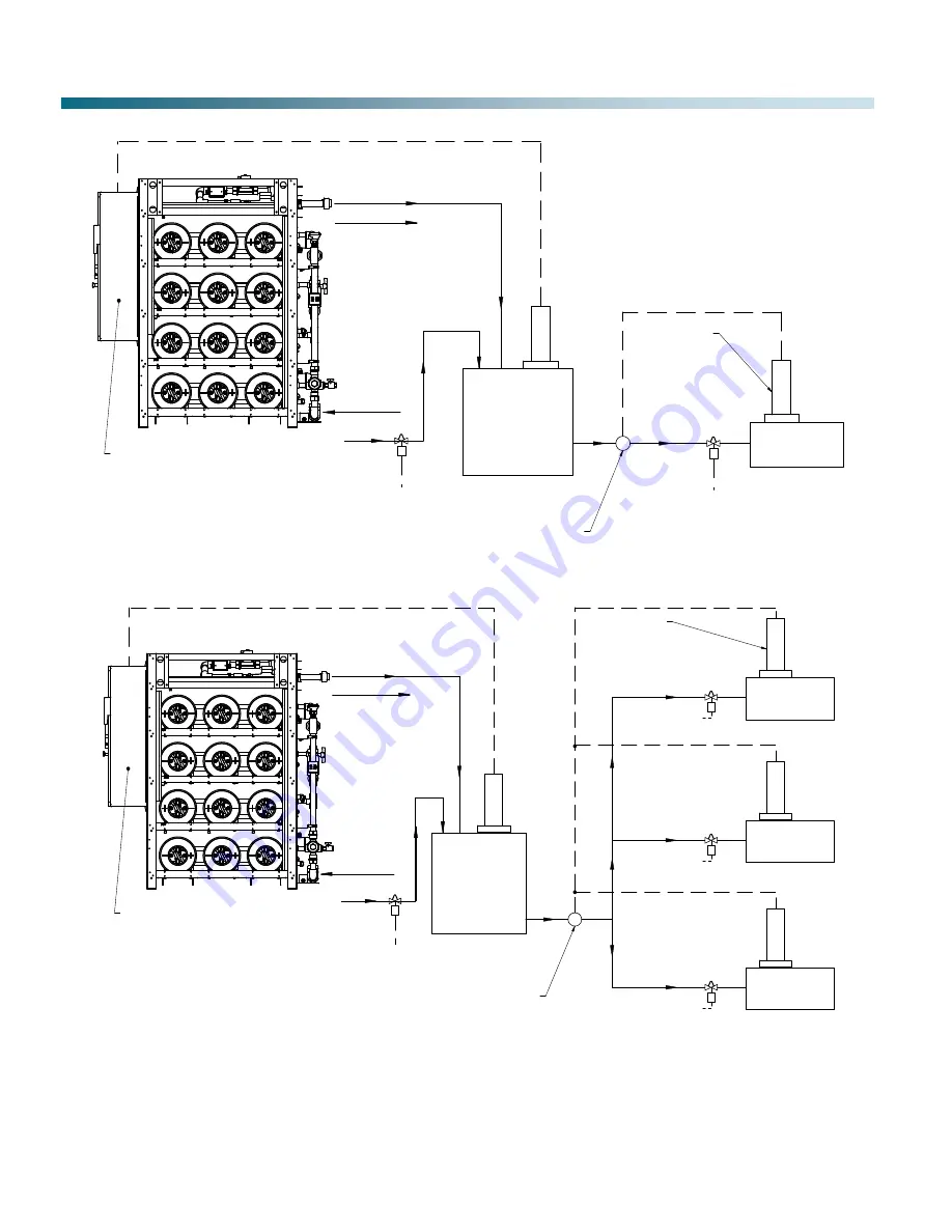
Figure 7: EWS Field Piping/Wiring for Multiple Evaporative Units with Makeup Tank

BOOSTER PUMP REQUIRED

(BY OTHERS)

S

EWS

MAKE UP TANK

MAKE UP

BYPASS

CLEAN OUTLET, PIPE TO PROCESS

FLUSH OUTLET, PIPE TO DRAIN
(NOT IN VIEW)

EWS CONTROL
PANEL

P

E
W
L
C

POWER AND CONTROL WIRING

EWLC REQUIRED

EVAPORATIVE UNIT

S

E
W
L
C

POWER AND CONTROL WIRING

WIRE TO EWLC

ON UNIT

EVAPORATIVE UNIT

BOOSTER PUMP REQUIRED

(BY OTHERS)

EWLC REQUIRED

(TYPICAL)

S

EWS

MAKE UP TANK

MAKE UP

BYPASS

CLEAN OUTLET, PIPE TO PROCESS

FLUSH OUTLET, PIPE TO DRAIN
(NOT IN VIEW)

EWS CONTROL

PANEL

WIRE TO EWLC

ON TANK

P

S

E
W
L
C

POWER AND CONTROL WIRING

E
W
L
C

S

E
W
L
C

S

E
W
L
C

WIRE TO UNIT EWLC

POWER AND CONTROL WIRING

POWER AND CONTROL WIRING

POWER AND CONTROL WIRING

EVAPORATIVE UNIT

EVAPORATIVE UNIT

WIRE TO UNIT EWLC

WIRE TO UNIT EWLC

Figure 6: EWS Field Piping/Wiring for Single Evaporative Unit with a Makeup Tank 

WIRE TO EWLC

ON TANK

Summary of Contents for Water Saver EWS-22

Page 1: ...WATER SYSTEMS Installation Operation Maintenance Manual For EVAPCO Water Saver TM ...

Page 2: ...the EWLC and Bypass Solenoid 14 Components 15 Water Flow Path 16 Pressure Regulator Valve 16 Water Meters 16 Conductivity Probe 16 Panel Wiring Locations 17 Operation 17 Startup Program 17 Main Program 17 Shutdown Program 17 Five Probe Electronic Water Level Control 18 EWS Start Stop 18 EWS Bypass 18 Hi Level Alarm By Others 18 User Display 18 Touch Screen Display 18 Home Screen 19 Operating Data ...

Page 3: ...eatment system that offers the following benefits x Improves Evaporative Cooling Water Efficiency by Increasing Operating Cycles of Concentration x Reduces Blowdown and Treatment Chemicals Sent to Drain x Low Cost of Ownership x 75 85 Recovery Rate Standard Equipment and Operation The Water Saver system is comprised of a control panel ion removal cylinders flow sensor conductivity probes and inter...

Page 4: ...13 1 12 18 30 EWS 53 115 46 1 2 83 1 4 230 480 36 5 23 1 15 22 37 EWS 54 115 46 1 2 83 1 4 230 480 36 5 23 1 20 30 50 EWS 63 130 46 1 2 83 1 4 230 480 36 5 23 1 18 27 45 EWS 64 130 46 1 2 83 1 4 230 480 36 5 23 1 24 36 60 Notes 1 Unit is designed for indoor installation 2 A sanitary drain is required to dispose flush cycle water 3 Inlet water pressure requirement Min 65 psi Max 120 psi 4 Electrica...

Page 5: ...bed onto the charged capacitor A 50 ion reduction allows the operating cycles of concentration to be safely doubled without an increase in scale or corrosion potential Figure 3 describes the capacitive deionization process Figure 4 shows an up close view of a cylinder Figure 3 Illustration of EWS Cycles Figure 4 Illustration of EWS Cylinder Principle of Operation Makeup water flows into a cylinder...

Page 6: ...en makeup water demand is sensed and stops operation when demand is satisfied see Figure 5 If the system uses a makeup tank supplied by EVAPCO the EWLC supplied by EVAPCO on the tank will start and stop Water Saver operation see Figure 6 or Figure 7 Makeup water bypass piping and control valve are supplied and field installed by others and are required to ensure the evaporative unit s will always ...

Page 7: ...ING WIRE TO EWLC ON UNIT EVAPORATIVE UNIT BOOSTER PUMP REQUIRED BY OTHERS EWLC REQUIRED TYPICAL S EWS MAKE UP TANK MAKE UP BYPASS CLEAN OUTLET PIPE TO PROCESS FLUSH OUTLET PIPE TO DRAIN NOT IN VIEW EWS CONTROL PANEL WIRE TO EWLC ON TANK P S E W L C POWER AND CONTROL WIRING E W L C S E W L C S E W L C WIRE TO UNIT EWLC POWER AND CONTROL WIRING POWER AND CONTROL WIRING POWER AND CONTROL WIRING EVAPO...

Page 8: ...onnect makeup line to evaporative unit x 3 self aligning connection on top of tank for custom 5 probe EWLC Clearance above the top of the tank is required for placement of EWLC probes refer to Table 2 for standard tank sizes EWS inlet water should be directed downwards away from the EWLC probes Depending upon the height of the mechanical room the 5 probe EWLC may need to be installed prior to movi...

Page 9: ...o the solution tank A sanitary sewer drain will be used during the CIP process The pump comes equipped with standard 120V maleplug The Water Saver has a GFCI utility outlet for this purpose Refer to Figure 9 for CIP layout Figure 9 CIP Equipment Operational Chemical Feed The Water Saver may require a chemical feed addition as part of the operating program to maintain performance A small chemical f...

Page 10: ...is lifted from the frame Use caution when moving the EWS The control panel is heavy and can cause the skid to tip Lifting Brackets are located on each corner of the frame Mounting Foot Plates Lagging the Water Saver to the mechanical room floor is recommended Mounting foot plates with holes are located on the EWS frame Refer to Figure 10 for lifting and mounting locations Figure 10 Lifting and Mou...

Page 11: ...ow from the EWS is plumbed to either the evaporative unit or the makeup tank Due to pressure drop across the EWS up to 15 psi some installations may require an inline booster pump supplied by others to get the outlet water flow to the desired destination A booster pump supplied by others is required when a makeup tank is used to supply makeup to the evaporative unit s A totalizing water meter is f...

Page 12: ...eter x In most applications the recommended cycle time for the bypass valve is 15 25 seconds line size and pressure may affect recommended cycle time x On the outlet side the bypass line must run all the way to the tower for configurations without a makeup tank See Figure 5 Figure 7 for examples of typical bypass piping configurations Wire the bypass valve to the 5 probe EWLC as shown in Figure 14...

Page 13: ...Bypass Solenoid Figure 14 shows wiring for a single EWS running off a single EWLC Internal wiring to be done by others For other configurations please contact your local Evapco Representative Figure 14 EWLC Wiring Diagram for a Single EWS Running off a Single EWLC ...

Page 14: ...omponents Clean Outlet Valve Flush Outlet Valve Pressure Sensor Magnetic Flow Meter Sample Port Inlet Conductivity Probe Clean Outlet Water Meter Outlet Conductivity Probe CIP Inlet Flow Control Valve Pressure Regulator Valve Main Inlet Isolation Valve Drain Isolation Valves Makeup Inlet Water Meter CIP Outlet ...

Page 15: ...n reduced clean outlet water path and the blue dashed arrows show the makeup inlet path Figure 16A EWS Water Flow Path Cylinder Plumbing Figure 16B EWS Water Flow Path Inlet Outlet Piping Control Panel Flush Outlet Water Ion Reduced Clean Outlet Water Makeup Inlet Water Flush Outlet Water Ion Reduced Clean Outlet Water Makeup Inlet Water ...

Page 16: ... not exceed 120 psi inlet pressure Water Meters Meter is installed horizontally with register facing up N O reed switch set at 10 gallons per count is mounted on the dial face and connected to the control panel Conductivity Probe The EWS comes with an Inlet Conductivity Probe and an Outlet Conductivity Probe See maintenance requirements in Table 4 Panel Wiring Locations In Figure 17 Valve Connecti...

Page 17: ...lected ions from the superconducting capacitors The Shutdown program automatically engages when the Water Saver receives a signal from the EWLC that water demand has been satisfied Once Shutdown steps are complete the Water Saver awaits a signal to restart Standby If a start signal is received by the Water Saver during the Shutdown steps the Shutdown program will complete before the Water Saver re...

Page 18: ...een treated by the EWS and may affect desired cycles of concentration Hi Level Alarm By Others The 5 probe EWLC is equipped with a high water level relay and probe High water level is sensed when the high alarm probe tip is submerged The high alarm relay can be connected to a user supplied device such as a warning light or audio alarm Note Refer to Troubleshooting section if high level alarm frequ...

Page 19: ... displays alarm history When an alarm condition occurs a pop up window alerts the user of a new alarm To acknowledge a current Alarm select the Acknowledge icon The new alarm is added to the Alarm History Alarms can be reset by selecting the Reset icon Figure 20 Sample Alarm Overview Screen Alarm Configuration Alarms are preset from the factory for seven operating attributes to alert users of syst...

Page 20: ... to EWS To turn off the Water Saver perform the following x Move the service disconnect handle on the Control Panel to the OFF position Restarting Power To restart the Water Saver perform the following x Move the service disconnect handle on Control Panel to the ON position x Wait for the Home screen to be displayed 20 seconds x Place system in Automatic Mode o Select Begin Auto Operation icon Rou...

Page 21: ...te setting Clean conductivity value close to makeup conductivity value Conductivity probe s out of calibration Calibrate probe s Conductivity probe s fouled Clean probe s EWS power supply off Reset power supply Turn off main power for 1 minute then restart refer to Turning Off Power to EWS Cylinder fouling CIP Required Contact Factory Authorized Service Provider Dark display screen Screen display ...

Page 22: ...AIR REPLACEMENT OR REFUND IS THE APPROPRIATE REMEDY IF EVAPCO DECIDES TO MAKE REPAIRS EVAPCO HAS THE OPTION OF COMPLETING ALL NECESSARY REPAIRS ITSELF OR AUTHORIZING A THIRD PARTY TO PERFORM SUCH REPAIRS AT EVAPCO S EXPENSE EVAPCO IS NOT RESPONSIBLE FOR ANY REPAIR WORK PERFORMED BY A THIRD PARTY THAT EVAPCO DID NOT PRE APPROVE IN WRITING EVAPCO IS ONLY RESPONSIBLE FOR COSTS THAT PERTAIN TO REPAIR ...

Page 23: ...EVAPCO Inc World Headquarters PO Box 1300 Westminster MD 21158 410 756 2600 EVAPCO INC 2021 All Rights Reserved ...

Reviews: