Introduction:
This product can be operated in any Z-Wave network with other Z-Wave Plus™ certified devices from other manufacturers.
All non-battery operated nodes within the network will act as repeaters regardless of vendor to increase reliability of the network.
Each module is designed to act as a repeater,which will re-transmit a radio frequency (RF) signal by routing the signal
around obstacles and radio dead spots to ensure that the signal is received at its intended destination.
ZW12 is a security enabled Z-Wave Plus™ device. A security Enabled Z-Wave Plus™ Controller must be used in order to fully utilize the product.
The Device Type of the ZW12 is on/off power switch.
The Role Type of the ZW12 is Always On Slave Role Type
Key Features:
---Remote ON/OFF control via the Z-Wave™ controller
---Manual ON/OFF control with the front panel push button
---Support Association Group and Auto Report switch status
---Support firmware upgrades via Over-the-air (need Gateways support)
---Support Scenes
Product Overview:
A. Push button
B. Status LED
C. POWER INPUT DC:5V
D. Connect the switch
E. Relay Output
Indicator Command Class
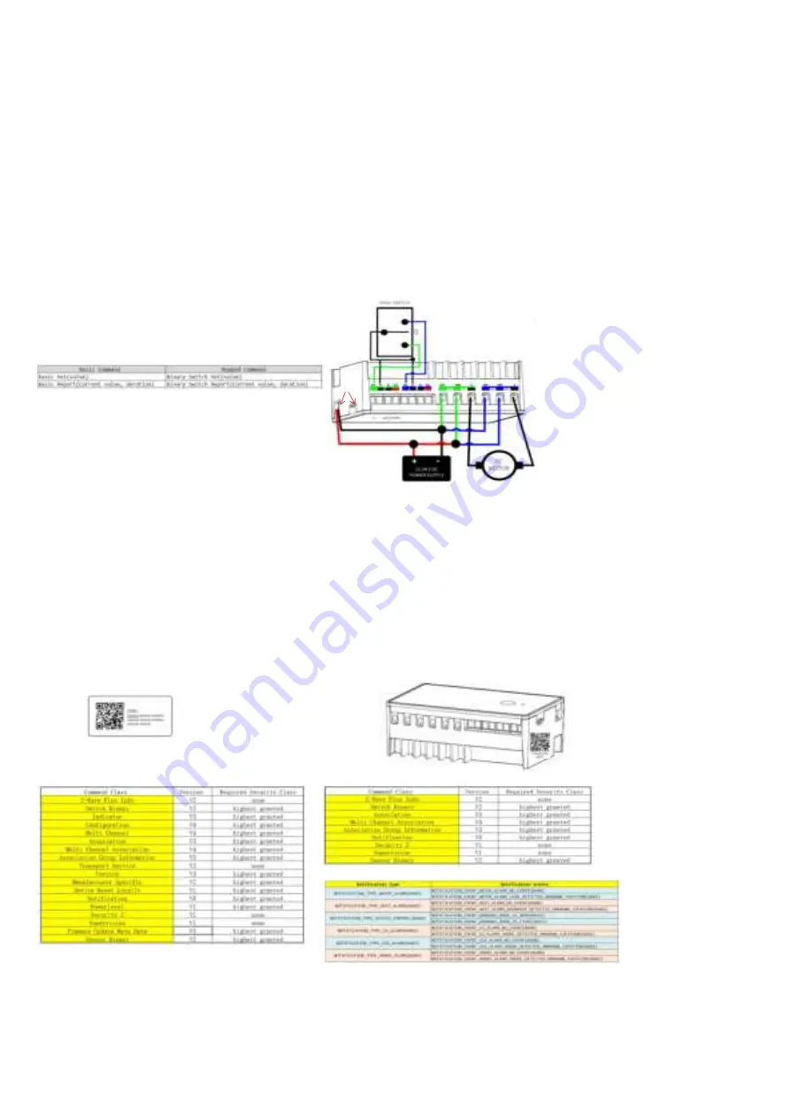
ZW12 Installation Wiring Diagram
* The indicator (blue color) will flashes according the indicator set
command received from HUB.
Basic command class
* The basic set command class is mapping to binary switch set.
* Basic set will control both two endpoints' relay to turn on or turn off.
Key function description
Function 1: press and hold for more than 5s,change SW1 mode
Function 2: press 2x and hold for more than 5s,change SW2 mode
Function 3: quickly press 3x Button: ADD(inclusion) OR Remove( exclusion)
Function 4: press 5x change led parameter
Function 5: press 4x, then LED lit for 4s, within this time press 4x again – LED blinks 3 times then off to FACTORY RESET
(Node:Please use this procedure only when the network primary controller is missing or otherwise inoperable.)
Adding Your Device To A Hub
The device support two methods of inclusion,When using a Z-Wave Plus™ certified controller choose Network Wide Inclusion or SmartStart,
Network Wide Inclusion To A Z-Wave™ Network
1,Refer to your primary controller instructions to process the inclusion / exclusion setup procedure.
2,When prompted by your primary controller, click the Up or Down button three times in one second.
The device is compatible with SmartStart
SmartStart enabled products can be added into a Z-Wave network by scanning the Z-Wave™ QR Code found on the top of the outlet or the back of
the box with a controller providing SmartStart inclusion.No further action is required and the SmartStart product will be added automatically within
10 minutes of being switched on and in the network vicinity.
QR CODE
the QR code are sticked to the side of the case,DSK is included in the QR code.
DSK
The DSK code can be found on the DSK label which is attached on the packaging box.
Command Class
[ROOT ENDPOINT]
ENDPOINT 1& ENDPOINT 2
Notification Type and events
[NOTES]:
1)For the root endpoint, the Notification and Sensor Binary only supported when the parameter 2 is set to 4~9 or the parameter 3 is set to 4~9.
(When one of input or both two inputs are used to sensor alarm.
2)For the endpoint 1, the Notification and Sensor Binary only supported when the parameter 2 is set to 4~9.
(When input (S1 and C) is used to sensor alarm.
3)For the endpoint 1, the Notification and Sensor Binary only supported when the parameter 3 is set to 4~9.
(When input (S2 and C) is used to sensor alarm.
A
C
D
E
B


