


Part number HA028582. Issue 6.0 May-07 13
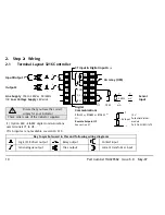
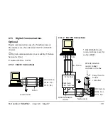
2.4
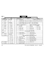
Wire Sizes
The screw terminals accept wire sizes from 0.5 to 1.5
mm (16 to 22AWG). Hinged covers prevent hands or
metal making accidental contact with live wires. The
rear terminal screws should be tightened to 0.4Nm
(3.5lb in).
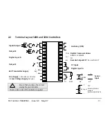
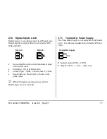
2.5
Sensor Input (Measuring Input)
•
Do not run input wires with power cables
•
When shielded cable is used, it should be grounded
at one point only
•
Any external components (such as zener barriers)
connected between sensor and input terminals may
cause errors in measurement due to excessive and/or
un-balanced line resistance, or leakage currents.
•
Not isolated from the logic outputs & digital inputs
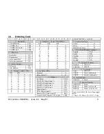
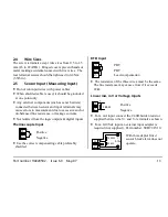
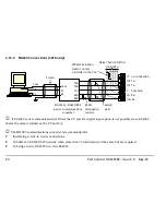
Thermocouple Input
Positive
Negative
•
Use the correct compensating cable preferably
shielded.
RTD Input
PRT
PRT
Lead
compensation
•
The resistance of the three wires must be the same.
The line resistance may cause errors if it exceeds
22
Ω
.
Linear mA, mV or Voltage Inputs
Positive
Negative
•
For a mA input
connect the 2.49
Ω
burden resistor
supplied between the V+ and V- terminals as shown
•
For a 0-10Vdc input an external input adapter is
required (not supplied). Part number: SUB21/IV10.
With this adaptor fitted
sensor break alarm does not
operate.
-
+
V+
V-
VI
V+
V-
2.49
Ω
-
+
V+
V-
100K
Ω
806
Ω
+
0-10V
-
V+
V-
Summary of Contents for 3200
Page 1: ...3200PID Temperature controllers User Guide Manuel Utilisateur Bedienungsanleitung ENG FRA GER ...
Page 57: ...3200Régulateurs de température PID Manuel Utilisateur FRA ...
Page 58: ......
Page 116: ...58 3200 Guide utilisateur HA028582FRA Indice 6 0 mai 07 ...
Page 117: ...3200PID Temperaturregler Bedienungsanleitung GER ...
Page 118: ......
Page 173: ......


