


&KDSWHU
#;#
7\SH
#;/#<#
DQG
#43#
,QYHUWHU
#
%UDNH
#
8QLW
#
,QVWDOODWLRQ
;05
8;7
6
2953
8.
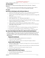
Remove drive top cover which is attached via 4 off M5 screws on the side and 2 off M5 screws on the
top. Care should be taken to keep the cover from falling into the drive and damaging the internal
components.
9.
Install brake unit IGBT/heatsink assembly within exhaust duct and tighten clamps.
10.
Connect brake unit control cable to the 14 way bulkhead connector at the top of the drive.
11.
Fit the brake connecting plate(s) to the phase joining tabs of the drive top phase (M3/U) with M6 screws
provided (finger tight only). This is achieved by placing the end of the connecting plate with threaded tabs
under the phase joining tabs (see figure 8.3).
12.
Fit the snubber capacitors (qty 2 size 8, qty 3 size 9, qty 4 size 10) over the brake joining plate(s) to the
IGBT using M6 screws (finger tight only) - see figure 8.3.
13.
Tighten all M6 screws on the brake connecting plate to 5 Nm (3.7 ft-lb).
14.
Fit earth bonding bracket to heatsink and duct connection/earthing screws (M5) to exhaust duct. Tighten
to 4 Nm (3 ft-lb). NOTE - This connection must not be omitted as it is required for safety reasons.
15.
Replace drive top cover, exercise care to not damage brake connection plates with the top cover as
this will compromise the electrical insulation. Tighten 4 off M5 screws on side of drive and 2 off M5
screws on top of cover to 2.5 Nm (1.84 ft-lb).
16.
Replace drive front top cover with 2 off
¥
turn fasteners.
17.
Fit brake unit cover with M6 captive washer nuts.
)LJXUH
#;14
This manual was downloaded on www.sdsdrives.com
+44 (0)117 938 1800 - [email protected]


