ISIS user manual
Issue E
48
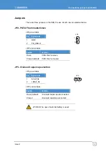
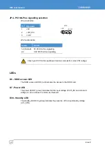
JP4 - PC/104-Plus signalling selection
JP4 pinout table:
Pin
Signal name
1 +5V
2 +VIO_PCI
3 +3.3V
JP4 function table:
Position
Function
1-2 (Default) 5V PC/104-Plus signalling
2-3
3.3V PC/104-Plus signalling
Check your PC104-Plus peripheral module’s manual for correct VIO voltage.
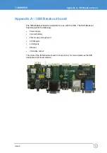
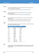
LEDs
D6 – SDIO access LED
The SDIO access LED D6 (red) indicates the access to the SDIO card.
D7 - Power LED
The power LED D7 (green) indicates that the input voltage (VCC5_IN) and on-board
v3.3V are above the minimum threshold.
D30 - Standby LED
The standby LED D30 (yellow) indicates the presence of the input standby voltage
(+V5_STB).
1
3
+5V
+3.3V
JP4
Summary of Contents for ISIS XL-1.1-M512-F2G-GPS-I
Page 58: ...ISIS user manual Issue E 58 ...
Page 60: ...www eurotech com ...

