Hardware specification
Issue E
21
Intel Atom processor is available in the following frequency SKU’s:
Product
Name
Frequency
TDP
Temperature
range
Package
Chipset Pairing
Z530
1.6GHz
2.2W
0C to +70C
BGA-441
13x14mm
Z510
1.1GHz
2W
0C to +70C
BGA-441
13x14mm
US15W (2.3W)
BGA-1249
22x22mm
Z530P
1.6GHz
2.2W
0C to +70C
XL BGA-437
22x22mm
Z510P
1.1GHz
2.2W
0C to +70C
XL BGA-437
22x22mm
US15WP (2.3W)
BGA-1295
37.5x37.5mm
Z520PT
1.3GHz
2.2W
-40C to +80C
XL BGA-437
22x22mm
Z510PT
1.1GHz
2.2W
-40C to +80C
XL BGA-437
22x22mm
US15WPT (2.3W)
BGA-1295
37.5x37.5mm
Expansion buses
PC/104-Plus bus interface
The PC/104-Plus bus interface on ISIS supports PCI local bus compatible peripherals, as
defined in the
PCI Local Bus Specification Revision 2.2
. This version of the PCI bus is
intended as a 32-bit bus running at 33MHz (as specified in the
PC/104-Plus Specification
Version 2.0)
.
A Tundra Tsi381 PCI Express (PCIe) to PCI bridge IC is used to implement the PCI bus
on the ISIS. The Tundra Semiconductor Tsi381 is a high-performance bridge that
connects the serialized PCIe protocol to the parallel PCI bus standard. It connects
directly to the PCIe x1 Port 1 provided by the US15W SCH on the CPU module.
Some additional glue logic is required to expand the PCI REQ#/GNT# capability. Four
REQ#/GNT# signal pairs are supported by Tundra Tsi381 device, and ISIS supports six
PCI devices (Ethernet controller, PCI/ISA bridge and four PC/104-Plus slots). The glue
logic is implemented in a CPLD.
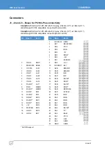
A standard stack through connector for the PCI bus (4x30-pin, 2mm pitch) is used for this
interface (as specified in the
PC/104-Plus Specification Version 2.0)
connector pin details.
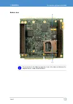
A shrouded connector is used on the bottom side of the PCB. The CPU module is fitted
on the top side of the ISIS PCB with 8mm standoffs, and uses the heat spreader to
support the module. In standard operation the ISIS is used on top of the PC/104-Plus
stack, however PC/104-Plus and PC/104 connectors on ISIS are accessible from the
topside if a PC/104-Plus extender standoff solution is used.
The ISIS supplies only the selected VIO voltage to the PC/104-Plus stack, as defined by
the
PC/104-Plus Specification Version 2.0
. +5V is also supplied to the stack directly from
the input power connector J9.
+12V and -12V are only available if you connect the +12V and -12V pins on the power
connector J9 to a supply, otherwise they must be supplied directly to the PC/104-Plus
stack. If you r3.3V, it must be supplied directly to the PC/104-Plus stack.
Summary of Contents for ISIS XL-1.1-M512-F2G-GPS-I
Page 58: ...ISIS user manual Issue E 58 ...
Page 60: ...www eurotech com ...

