

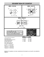
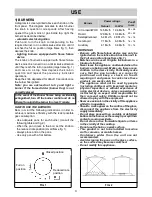


8
INSTALLATION
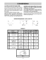
FIG. 4
COMPLY WITH THE DIMENSIONS
(in mm)
A
B
C
D
E
4F (60)
553
473
63.5
63.5
173.5 min.
5F (70)
645
475
63.5
63.5
173.5 min.
5F (90)
833
475
62.5
62.5
73.5 min.
TECHNICAL INFORMATION
FOR THE INSTALLER
This appliance shall be installed only by authorised
personnel and in accordance with the
manufacturer’s installation instructions, local gas
fitting regulations, municipal codes, electrical wiring
regulations, NZS5261:2003, AS 5601 - Gas
Installation and any other statutory regulations.
Ventilation must be in accordance with AS 5601,
NZS5261:2003 - Gas installation. In general, the
appliance should have adequate ventilation for
complete combustion of gas, proper flueing and
to maintain temperature of immediate
surroundings safe limits.
The wall and bench surfaces must be capable of
sustaining temperatures of 75 °C. All laminates,
fixing adhesive and surfacing materials should
be certified suitable for this temperature.
3) INSTALLING THE COOKTOP
Check that the appliance is in a good condition after
having removed the outer packaging and internal
wrappings from around the various loose parts. In
case of doubt, do not use the appliance and contact
qualified personnel.
Never leave the packaging materials (cardboard,
bags, polystyrene foam, nails, etc.) within
children’s reach since they could become
potential sources of danger.
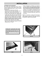
The measurements of the opening made in the top of
the modular cabinet and into which the cooktop will be
installed are indicated in fig. 4. The maximum overall
dimensions are shown either in Figures 4/A - 4/B - 4/C.
Always comply with the measurements given for
the hole into which the appliance will be recessed
(see fig. 4).
The appliance belongs to class 3 and is
therefore subject to all the provisions
established by the provisions governing such
appliances.
Any adjoining wall surface situated within 200 mm
from the edge of any hob burner must be a suitable
non - combustible material for a height of 150 mm
for the entire length of the hob. Any combustible
construction above the top of the burner and no
construction shall be within 450 mm above the top
of the burner. A minimum depth of 70 mm from the
top of the work surface must be provided for this
appliance.
CAUTION:
the installer shall test the appliance
before leaving. Test the safety
operation of the ignition system on all
burners individually and combined.
IMPORTANT: a perfect installation,
adjustment or transformation of the cook top
to use other gases requires a QUALIFIED
INSTALLER: a failure to follow this rule will
void the warranty.
Fig.4/A
Mod.:GOC64
Fig.4/B
Mod.:GOC75
Fig.4/C
Mod.:GOC95


