Euroheat Edition D N1087 The Flue Manual Download Page 7

©


EUROHEAT


DISTRIBUTORS (H.B.S) LTD. March 2006

Technical Guide IN1087 Edition  C

4

A flue system for an open fire has an enormous margin for design error because it receives so much 

of the heat generated by the fire, and the fire is not expected to be controlled beyond the rate at which 

it is refueled. The efficiency of a stove is achieved because  less of the heat generated by the fire is 

lost to the flue, and that the flue design  allows  consistent control of the fire.  These impose design 

constraints which become progressively more restrictive as the stove’s efficiency increases.  With 

less motivation the flue route taken must provide the smoothest path possible to retain as much of 

the heat in the gases as possible.

If we look at the flue’s prime function, which is to remove the harmful products of combustion, we find 

that even the chemicals themselves  become more difficult to deal with at reduced flue temperatures. 

One of the more  important chemicals formed by the combustion process is oxygen dihydrate, a 

chemical  better known as water. The ability of the gases to  “absorb”  water is dependent on their 
temperature  and    when  the  gases  are  “saturated”,    the  water  will  begin  to  condense  out  as  the 
temperature falls.  The point at which the water will be shed by the gases  is known as the “dew 
point”,  but unlike the picturesque dew covered image of dawn, this condensate will  combine with 

all the nasty acidic chemicals in the flue gases as it runs down the flue wall.  Evidence of this can be 

seen on the walls of old  properties where this acidic water has been absorbed by the masonry flue 

and has eaten away the lime mortar. This will be worse where the flue has been for a range or oven 

which take out more heat from the fire. If the fire has been primarily fueled with wood, the creosote 

and resinous tars may even reach the internal plaster not only staining them but posing a fire risk 

because these tars are combustible. The flue needs to maintain the gases above the dew point 

and this is  achieved by making the flue as smooth as possible to reduce any friction between the 

wall and the gases which will allow the smallest possible diameter to be used and so minimize the 

surface area through which heat may be lost. A flue constructed from stainless steel satisfies all the 

requirements because it is smooth, impervious to the chemicals, its low mass allows rapid warming 

and it can be easily cleaned. Flexible metal flue liners should be installed in one unbroken length. 

Other than the sealing at the top and bottom the void between the flue and the chimney should be 

left empty except in circumstances where the void is deamed to be large.

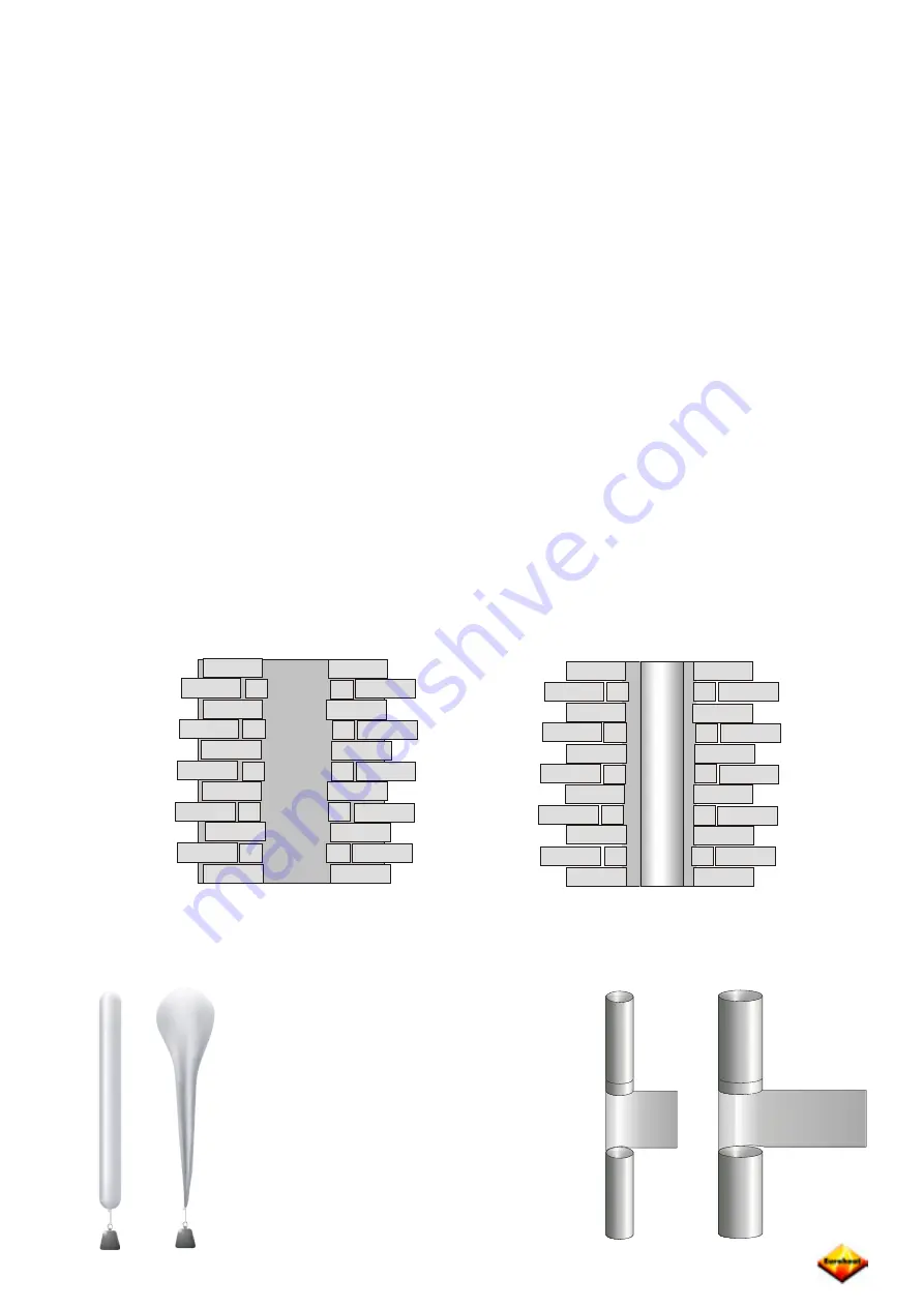
Existing chimneys should have a stainless steel liner fitted. If the void between the liner and masonry 

is large it may be filled with vermiculite to provide insulation it will then reach its operating temperature 

more rapidly. Where no chimney exists, a twin walled, interlocking stainless steel system should be 

used. The walls are separated by an insulating material. 

An appliance produces a known quantity 
of  hot  gases,  capable  of  generating  a 
flue  draught,  whatever  the  flue  size,  if 
its  temperature  difference  is  maintained. 

All  flues  allow  heat  loss  and  reduce  the 

potential available. To reduce heat lost from 

the flue the most basic design consideration 

is to ensure its surface area  is kept to a 

minimum, by fitting the smallest diameter  

recommended for the appliance.  

Summary of Contents for Edition D N1087

Page 1: ...EUROHEAT DISTRIBUTORS H B S LTD March 2006 Technical Guide IN1087 Edition C 1 The Flue Guide 3 7 Conventional Flue Systems IN1087 Edition D...

Page 2: ...125 mm to 6 or 150 mm is an increase of 44 5 or 125 mm to 7 or 175 mm is an increase of 228 6 or 150 mm to 7 or 175 mm is an increase of 38 5 Pipe Diameter Cross sectional area 4 or 100 mm 11 7 sq or...

Page 3: ...e IN1087 Edition C Flue Flue liner Thermal insulation Outer wall Chimney section Cladding Chimney fitting Connecting flue pipe Heating appliance Chimney Multi wall CHIMNEY TERMINOLOGY Not identified i...

Page 4: ...DISTRIBUTORS H B S LTD March 2006 Technical Guide IN1087 Edition C Conventional Gas Flue Installation A B C A Twin wall insulation internal to property B Top flue routed externally C Rear flue routed...

Page 5: ...EUROHEAT DISTRIBUTORS H B S LTD March 2006 Technical Guide IN1087 Edition C Chimney Construction...

Page 6: ...tly the flow induced by the difference in temperature between the gases within the flue and that of the air outside the flue and secondly the flow of wind around the property and the flue termination...

Page 7: ...he lime mortar This will be worse where the flue has been for a range or oven which take out more heat from the fire If the fire has been primarily fueled with wood the creosote and resinous tars may...

Page 8: ...used by multiple flues and differences in flue heights and again the effects will become evident even before any fire is lit All the flues will tend to aspirate as in the previous example but with inc...

Page 9: ...s across the flue terminal it induces flue draught which if we are to maintain a quantifiable air supply to our stove it needs to be controlled If wind caused an air stream which was consistent in all...

Page 10: ...d not only is the depth of high pressure far deeper than has been presupposed the turbulence and pockets of varying pressures are more unpredictable Again the following drawings are simplistic but the...

Page 11: ...every builder liked working at high altitudes Ask about smoking fires and try to relate the problem with wind direction and features which may cause turbulence over an area rather than just the proper...

Page 12: ...be set to limit the negative pressure at any point below the stoves maximum rate the flue will probably be unable to achieve pressure required for the maximum rate If the flue induces too much negativ...

Page 13: ...Before dismissing the simple rain cap cowl it must be remembered that we have given no consideration to effects the house itself will have on the wind direction and those together with other pressure...

Page 14: ...ing the diameter of the box to prevent this will only increase the negative pressures generated at the downwind side Another solution to the problem of varying wind speed is to direct air passing over...

Page 15: ...ly the differing sizes and shapes of the dishes means that their influence will not remain consistent with each for all wind speeds and all directions No cowl will solve all problems and no cowl will...

Page 16: ...mn water that the pressure will support A water filled manometer is a graduated tube of water and is used to measure gas pressure by directly connecting its vertical column of water to a pressure test...

Page 17: ...hand scale is read If the inlet is closed and the inlet is through the restricted orifice the right hand scale is used 02 01 03 04 05 06 07 08 09 IN OF WATER DRAFT OR PRESSUR E LOW RANGE IN OF WATER D...

Page 18: ...this has to be weighed against the heat losses from the larger diameters A complex flue may look impressive but its performance will be disappointing It will not give the performance of the taller ve...

Page 19: ...liner support collar Weatherproof chimney capping and pot Sound chimney brick work Stainless steel liner Flexible to single wall adapter Register plate preventing the escape of heat positioned as low...

Page 20: ...dition C 17 MGOOIFIG65 X X Access for cleaning minimum horizontal path With no flue liner fitted and positioned on an unstable hearth makes sealing the flue reliably in this sort of installation impos...

Page 21: ...least 2300mm Outlets should be above the shaded areas Area Location of flue outlet A at least 1800 mm vertically above the weather surface and at least 600 mm above the ridge B at least 1800 mm vertic...

Page 22: ...ormance class of at least FB4 N2 Flue block chimneys should be installed with sealed joints in accordance with the flue block manufacturer s installation instructions Where bends or offsets are requir...

Page 23: ...would be to follow the guidance in the enclosed table Where a flue pipe or chimney penetrates a fire compartment wall or floor it must not breach the fire separation requirements of Approved Document...

Page 24: ...heck Is there safe and adequate access to the chimney Can the cowl be fitted with out the need for scaffolding or lifting equipment bearing in mind current health and safety regulations Is there a sui...

Page 25: ...er extend to the top of the chimney pot If the liner terminates at the base of the pot the cowl may not perform as it is designed to do due to turbulance formed inside the pot If the liner is fitted c...

Page 26: ...other obstructions Please refer to the manufacturers instructions regarding the assembly and correct fitting of the cowl Most cowls have been designed to be fitted to a pot and not directly onto a fl...

Page 27: ...and locking bands available as an optional extra Finally having fitted your cowl carry out necessary checks to ascertain that the appliance is working correctly Re commission the appliance if this is...

Page 28: ...on a rear exit 6 Avoid long external runs 7 The warmer the flue the better it works 8 Terminate above the ridge 1 metre is ideal where possible 9 Fit the correct terminal and as per the manufacturers...

Page 29: ...ment X This is an unsatisfactory flue firstly because the termination is too close to the roof ridge which will subject it to turbulence and secondly because it has no easy access for cleaning and the...

Page 30: ...ely vertical aspect with no bends no horizontal runs and protected from damage Particular attention must be payed to any building regulations which may be applicable and you must be aware of any restr...

Page 31: ...motivation During the very changeable whether conditions of Spring and Autumn the outside temperature can rise suddenly and become warmer than the temperature within the house This causes the air wit...

Page 32: ...l If lighting the stove under these conditions proves to be more than an infrequent irritation you might like to consider purchasing a flue heater band which is permanently attached to the flue pipe a...

Page 33: ...pressure drop within the property The converse is also true as the relationship of the openings to the wind direction are reversed Various attempts to cancel the effects of the winds effects upon air...

Page 34: ...e of the vent is dangerous and must not be done Although the ideal position for the air vent inlet is as close to the stove as possible to minimise cold draughts in the room care must be taken to ensu...

Page 35: ...EUROHEAT DISTRIBUTORS H B S LTD March 2006 Technical Guide IN1087 Edition C 32 Notes...

Page 36: ...Distributors H B S Ltd Unit 2 Court Farm Business Park Bishops Frome Worcestershire WR6 5AY Telephone 01885 491100 info euroheat co uk www euroheat co uk Euroheat are suppliers are the Harmony Stanfor...

Reviews: