EUROCOM 5100-C DeskNote Lite User Manual Download Page 28

2-8

User's Manual

!

!

!

!

 Using Hard Disk Drive

The hard disk drive is mounted in a removable case and can be taken out
to accommodate other 2.5” IDE hard disk drives with a height of 12.7mm.
The system supports PIO mode 4, Master mode IDE, LBA mode and
provides a high performance data transfer rate at speeds up to 33
Mbytes/second (ATA-33).
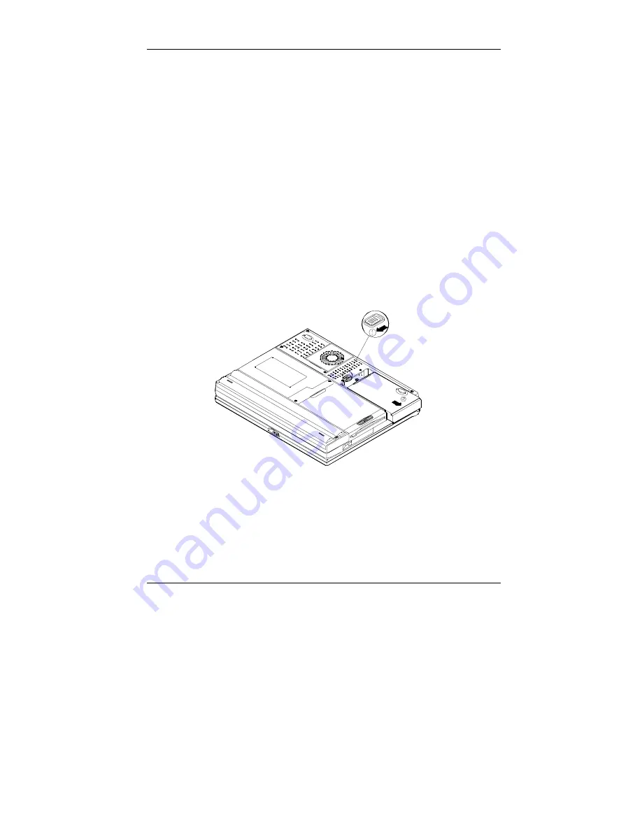
Removing

1. 

Turn the system power off.

2. 

Turn the computer over.

3. 

Locate the Hard Disk Drive latch.

4. 

Press the latch in the indicated direction and take the hard disk drive
out of the computer (Figure 2-10).

Note:
When inserting the hard disk drive, insert it firmly into the computer.  Make
sure you feel the drive click into the position when it is seated properly.


Figure 2-10

Summary of Contents for 5100-C DeskNote Lite

Page 1: ...in advance or afterwards 1999 Trademarks DeskNote is a registered trademark of Eurocom Corporation IBM PC OS 2 PS 2 EGA and VGA are registered trademarks of International Business Machines Corporatio...

Page 2: ...e 1 8 System Status LED Indicators 1 10 Power Button 1 10 Rear View 1 12 Left Side View 1 14 Infrared 1 15 Right Side View 1 16 5 25 CD ROM Drive 1 16 Ventilation 1 16 Chapter 2 Operation2 1 Replacing...

Page 3: ...ces 2 24 Attaching a Security Lock 2 24 Attaching a Parallel Printer 2 25 Attaching a TV Set 2 26 Attaching a USB compatible Device 2 27 Attaching a Serial Mouse 2 28 Attaching an External Monitor CRT...

Page 4: ......

Page 5: ...he short instruction on your DeskNote computer system that will help you to get the basic understanding about the computer Unpacking Operating Environment Powering the System By AC Power Adapter By Ba...

Page 6: ...uter and the included accessories Figure 1 1 Check the items one by one If there is something wrong contact your dealer immediately DeskNote Computer Carrying Bag Power Adapter Power Cord User Manual...

Page 7: ...pment proper care and operation of your computer will prolong the use period Make sure that the computer is not Exposed to excessively heat or direct sunlight Shocked or vibrated Exposed to strong mag...

Page 8: ...omputer An incorrect type of power adapter will cause damage to the computer and its components 1 Plug the power adapter cord into the AC in socket on the rear panel of the computer 2 Connect the powe...

Page 9: ...ion time is related to the application and the configuration you re using Inserting 1 Turn the computer over 2 Fit the battery pack firmly into the computer 3 The latch will click into the place when...

Page 10: ...cover Figure 1 6 2 Lift the top cover to reveal the LCD panel and keyboard Figure 1 7 3 Adjust the LCD panel to a comfortable viewing angle 4 Press the power button to turn the system on or off refer...

Page 11: ...attery power is used while the system is turned on Red AC power is used while the system is turned on Green Battery is fully charged Red Battery is being charged Blinking Red Battery power is critical...

Page 12: ...s Two built in speakers provide 3D stereo sound system Trackpad and Buttons The pointing device features a sensitive glide pad for precise movements It functions like a two button mouse does The right...

Page 13: ...1 9 Chapter 1 Getting Started Figure 1 9 Microphone LCD Panel Trackpad and Button Stereo Speakers Keyboard...

Page 14: ...d Blinking Red Battery power is critically low Green The system has entered the configured suspend mode Green The embedded numeric keypad feature is activated Green The Caps Lock feature is activated...

Page 15: ...1 11 Chapter 1 Getting Started Note After turning off the system wait for a few seconds to power it on again LED Indicators Figure 1 10 Power Button Figure 1 11...

Page 16: ...tandard NTSC PAL for video display please refer to Chapter 3 Components Menu for more information USB Port The Universal Serial Bus USB port simplifies the expansion capability for peripheral devices...

Page 17: ...d to support the built in modem To use the function attach a phone line to the jack and insert a modem card optional into the modem socket on the mainboard Figure 1 12 AC in Socket Phone Jack PS 2 Typ...

Page 18: ...accepts any 2 5 hard disk drive with a height of 12 7mm or less The system supports Master mode IDE and PIO mode 4 ATA 33 Ultra DMA 3 5 Floppy Disk Drive The computer provides a built in 3 5 3 mode 1...

Page 19: ...nfrared compatible device The infrared port supports IrDA HPSIR 1 0 mode and Amplitude Shifted Keyed IR ASKIR mode For further information please refer to the manual of the wireless device you wish to...

Page 20: ...is located in the middle of the front cover of the CD ROM drive Pressing it will release the CD tray Ventilation The computer vents were designed to help dissipate system s heat produced during norma...

Page 21: ...ponents of the computer remove the battery and disconnect the AC power adapter Make sure you wear an anti static wrist strap to ground yourself before working with or repair the internal components St...

Page 22: ...r applications running on advanced operating systems such as Window 95 98 Window NT and UNIX Replacing the Processor 1 Remove all the power sources AC power and battery 2 Turn the computer over 3 Remo...

Page 23: ...2 3 Chapter 2 Operation Reinstalling Heat Sink Reinstall the CPU in the reverse order of removal Make sure that the heat sink cable is properly installed Figure 2 2 2 3 Figure 2 2 Figure 2 3...

Page 24: ...pe The computer supports EDO and SDRAM operation The total memory size is automatically detected by the POST routines To expend the memory you have the following choice with different SDRAM combinatio...

Page 25: ...tches to elevate the keyboard from its normal position Figure 2 4 3 Carefully lift the keyboard assembly out to expose the mainboard Locate the memory sockets Figure 2 6 Figure 2 7 Bank 0 Bank 1 Figur...

Page 26: ...rmal position Figure 2 4 3 Carefully lift the keyboard assembly out to expose the mainboard Locate the memory sockets Figure 2 7 4 Insert the memory module at a slight angle 45 and fit its connectors...

Page 27: ...e keyboard from its normal position Figure 2 4 3 Carefully lift the keyboard assembly out to expose the mainboard Locate the memory sockets Figure 2 7 4 Gently pull the two latches outward on both end...

Page 28: ...s a high performance data transfer rate at speeds up to 33 Mbytes second ATA 33 Removing 1 Turn the system power off 2 Turn the computer over 3 Locate the Hard Disk Drive latch 4 Press the latch in th...

Page 29: ...nd replace with another one you need to remove the two screws on each side of the case Figure 2 11 The location of the two screws may be varied depending on different types of hard disk model Gently d...

Page 30: ...ed as drive A by default and can be used as a boot device if properly set in SCU please refer to Chapter 3 BIOS Utilities Inserting Removing Diskettes When using the floppy drive always insert your fl...

Page 31: ...m power off 2 Turn the computer over 3 Locate the cover between the floppy disk drive and the CD ROM module 4 Remove the two screws to release the cover Figure 2 13 5 Locate the floppy disk drive latc...

Page 32: ...ace the CD into the Disc Tray with label side facing up Push the CD tray in and you are ready to start The Busy Indicator will light up while data is being accessed or while an audio CD is playing Whe...

Page 33: ...Turn the system power off 2 Turn the computer over 3 Locate the cover between the floppy disk drive and the CD ROM module 4 Remove the two screws to release the cover Figure 2 13 5 Locate the CD ROM l...

Page 34: ...ess the CD ROM eject button the disc tray will pop out partially 3 Pull the disc tray out 4 Carefully load the CD into the disc tray with label side facing up Press it gently to ensure it fits into th...

Page 35: ...not touch the surface of the disc Use clean soft and dry cloth to remove dust or fingerprints Do not use pen to write on the surface Do not attach any paper or other materials to the surface of the di...

Page 36: ...The PC card sockets are located on the computer s right side and left side The socket on left side is named socket A which supports Zoom Video Port Inserting PC Cards 1 Open the access door 2 Align t...

Page 37: ...2 17 Chapter 2 Operation Figure 2 18 Figure 2 19 Socket A Eject Button Eject Button Socket B...

Page 38: ...press and hold the Fn key then press the appropriate function key Figure 2 20 Hot Keys System Features Fn F3 Expand LCD display Fn F4 Control display top center position Fn F6 Toggle CRT LCD LCD CRT T...

Page 39: ...ion Windows 95 Special Keys The keyboard provides two keys that have special functions in Windows 95 98 This key has the same functions as the secondary mouse does This key activates the Windows 95 St...

Page 40: ...2 20 User s Manual Using Numeric Keypad Your DeskNote features a 102 key keyboard with an integrated numeric keypad for easy numeric data input Figure 2 21 Figure 2 21...

Page 41: ...d Configuration and Power Interface ACPI The ACPI interface gives the operation system OS direct control over the power management and Plug and Play functions of a computer The operation system can pe...

Page 42: ...y is restored as you left it This saves time and battery power Caution Do not enter suspend mode when you are 1 Accessing any of the disk drives such as HDD FDD or CD ROM drives 2 Using the audio feat...

Page 43: ...will be the installed DRAM n plus 4MB integrated video RAM 0VMAKFIL Pn For example if the system DRAM is 32MB 0VMAKFIL will create a partition size of approximately 36MB 0VMAKFIL P32 Resume from STD M...

Page 44: ...to the computer through the ports or jacks on the rear panel of computer Attaching a Security Lock The security lock is equipped to protect your computer from being stolen To install the security loc...

Page 45: ...to the parallel port Figure 2 23 4 Insert the other end of the cable to the printer s connector Fasten the cable s connector 5 Turn on the printer and computer In addition you also need to install the...

Page 46: ...e video standard for video display Enter the System Configuration Utility SCU Components Menu to specify the appropriate TV mode Simultaneous display on external monitor CRT and TV is available You ca...

Page 47: ...er 2 Operation Attaching a USB compatible Device The computer provides a USB port for the connection of a USB compatible keyboard mouse or other devices Attach the device as shown below Figure 2 25 Fi...

Page 48: ...1 Turn the system power off 2 Connect the cable to the serial port on the rear of the computer 3 Tighten the screws that fasten the cable to the serial port Figure 2 26 4 Turn on the computer In addit...

Page 49: ...the external monitor simultaneously Enter the System Configuration Utility SCU to select the appropriate parameters or use the Fn F6 keys refer to Chapter 2 Using Hot Keys 1 Turn the system power off...

Page 50: ...perated with a PS 2 keyboard or mouse attached by means of the PS 2 transfer cable Attach the external keyboard or mouse as shown below Figure 2 28 Both PS 2 type ports on the rear panel of the comput...

Page 51: ...ers using the System Configuration Utility SCU Power on Self Test POST POST Message Normal Operation POST Message Error Detected System Configuration Utility SCU Information in the SCU Initiating the...

Page 52: ...operating system POST Message Normal Operation You will see the following message if no error exists after the POST is performed SystemSoft BIOS MobilePRO BIOS Version 1 01 2482 00 R1 00 tr02 Copyrig...

Page 53: ...y SystemSoft BIOS MobilePRO BIOS Version 1 01 2482 00 R1 00 tr02 Copyright 1983 1996 SystemSoft Corp All Rights Reserved 300 MHz Celeron with MMX CPU L2 Cache 128KB Installed 4 MB Video RAM SystemSoft...

Page 54: ...thin the System Configuration Utility Menu Bar Items Pull down Menu Items Startup Date and Time Fast Boot Boot Device Display Enable Battery Low Beep Enable LCD expand Mode Enable Power On Beep Enable...

Page 55: ...e Ctrl Alt and S keys simultaneously CTRL ALT S to enter System Configuration Utility The above message only lasts seconds If you miss it the computer will initiate the boot process You must reboot th...

Page 56: ...Configuration Utility Left arrow Right arrow Move to a menu bar item on the left Move to a menu bar item on the right The highlighted letter key Select menu bar item Move to the corresponding menu ba...

Page 57: ...d letter key Select pull down menu item Move to the corresponding pull down menu item Tab Select a control Move between the options Down Up arrows Change values Modify the settings Spacebar Enable dis...

Page 58: ...A Hard Disk C Boot Device CD ROM Drive Specify where the system boots from LCD Activate the system s LCD panel CRT Activate an external monitor LCD CRT Activate both the LCD and the CRT TV Activate a...

Page 59: ...er On Password Verify new Power On Password Boot Password Enable Password to Power On Set password for booting computer Users are authorized to start the system after entering correct password Enter o...

Page 60: ...ache controller L2 Cache Write Back Enable the LS write back cache Cached The process of shadowing copies instructions from system BIOS into RAM to improve system performance BIOS Shadow Not Cached Di...

Page 61: ...he drive types for the diskette drive A 2 88 Mb Drive Enabled Primary HDD PIO Mode Drive Enabled CD ROM DVD ROM PIO Mode Drive Enabled IDE Settings LS120 ZIP 2 nd HDD PIO Mode Enable enhanced IDE sett...

Page 62: ...for DOS mode and Non PnP OS Normal 16550 IrDA HPSIR ASK IR Mode Setting for COM B FAST IR Define the COM B hardware DMA 0 DMA 1 COM Ports DMA Setting for Fast IR DMA 3 Specify the Fast IR DMA configu...

Page 63: ...Do not support PS 2 mouse with the wheel button Enable Keyboard Numlock Disable Specify whether Num Lock is on or off at system boot time 2 cps 6 cps 10 cps 15 cps 20 cps Key Repeat Rate 30 cps Defin...

Page 64: ...3 14 User s Manual Figure 3 5 Components Menu...

Page 65: ...e and battery life Enable High Power Saving Disable Enable Disable the power saving to its highest which results in min performance but longest battery life 5 sec 10 sec 15 sec 20 sec 30 sec Disk Stan...

Page 66: ...ent to switch the system from a working state to the Soft Off state Suspend to Disk Suspend to RAM Suspend Type Powered on Suspend Specify the suspend mode for power management 1 min 5 min 10 min 20 m...

Page 67: ...ould be connected to the serial port Enable MODEM Ring Resume Disable Disable the above Enable Automatically suspend the system to disk upon a low battery condition Enable Battery Low Suspend Disable...

Page 68: ...the system Exit No Save Exit without saving any current changes Default Settings Restore the default settings the original ones found in ROM Restore Settings Restore the current setup settings to the...

Page 69: ...256KB Flash ROM SystemSoft Plug and Play 1 0a ACPI 1 0 Display SVGA flat panel 12 1 TFT S3 ViRGE MX AGP 1X 64 bit hardware 2D 3D Accelerator Graphics Engine TV out with Marco Vision V7 1 anti copy tec...

Page 70: ...t One serial port One parallel port LPT1 support ECP EPP 1 7a and 1 9 Infrared file transfer IrDA 1 0 ASKIR External CRT monitor One S Video jack for TV output One External keyboard mouse PS 2 type po...

Page 71: ...39 5mm h 2 8kg with Lithium Ion battery Keyboard 84 keys Win95 keyboard include numeric keypad Environment Temperature Operating 5 C 35 C Non Operating 20 C 60 C Humidity Operating 20 80 Non Operating...

Reviews: