background image


Make sure that all the parts indicated in the following list are present before unpacking the machine: 


Squeegee; 


battery box; 


battery jumper L = 25 cm, fitted with terminals and terminal covers; 


battery cable L = 51.5 cm, fitted with connector, terminals and terminal covers; 


battery charger on board the machine; 


two 12 Volt dry charge batteries (optional). 

NOTICE: brushes, discs and disc pad holders must be purchased separately. 


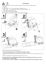
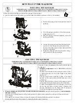
Follow the instructions below to unpack the machine: 
- connect the inclined ramp (position A) to the front part of the pallet, see figure 1; 
- tilt the machine slightly and place the wheel lifting plate (position B), see figure 1; 
- tilt the machine slightly again and place another wheel lifting plate from the other side of the machine (position C), see 

fig. 2; 

- remove the machine from the pallet along the inclined ramp (see fig. 3-4). 
 

CAUTION: DO NOT USE A FORKLIFT TO REMOVE THE MACHINE FROM THE PALLET AS IT MAY 
CAUSE DAMAGE TO THE MACHINE.


CAUTION: MOUNT THE BATTERIES ONLY AFTER REMOVING THE MACHINE FROM THE PALLET. 


UNPACKING


1


2


3


4


Summary of Contents for E51-BASE

Page 1: ... SERVICING 25 DRAINING AND CLEANING THE RECOVERY TANK 25 CLEANING INSTRUCTIONS ECO SYSTEM 26 DRAINING AND CLEANING THE SOLUTION TANK 27 CHECHING BRUSHES OR ABRASIVE DISCS 27 CLEANING THE DETERGENT SOLUTION FILTER 28 CLEANING THE PUMP OUTPUT PIPE FITTING 28 CLEANING REPLACING AND CHECKING THE INSTALLATION OF THE SQUEEGEE BLADES 29 CLEANING THE SUCTION FILTER 31 CHECKING THE BRUSH PLATE SPLASHGUARD ...

Page 2: ...eping your scrubber in tip top condition These are normal maintenance measures that any operator will be able to carry out with implements that he or she should normally have in the company In the case of particularly demanding work please call in specialised help OUR COMPANY AIMS AT THE CONSTANT IMPROVEMENT OF ITS PRODUCTS AND RESERVES THE RIGHT TO MAKE MODIFICATIONS AND IMPROVEMENTS WHEN IT CONS...

Page 3: ...N THE PERSON S ASSIGNED TO INSTALL OPERATE ADJUST CARRY OUT ORDINARY SERVICING CLEAN REPAIR AND TRANSPORT THE MACHINE OUR COMPANY WILL NOT BE HELD LIABLE FOR ANY PROBLEMS BREAKAGE ACCIDENTS OR OTHER OCCURRENCES DUE TO THE IGNORANCE OR THE NON APPLICATION OF THE PROCEDURES CONTAINED IN THIS MANUAL OR TO THE IMPROPER USE OF THE MACHINE FURTHERMORE OUR COMPANY SHALL NOT BE HELD LIABLE FOR THE CARRYIN...

Page 4: ...maintenance and cleaning operation must be carried out with the machine off with all the mechanisms still after the hot sections have cooled down and with the battery disconnected When using compressed air guns for cleaning protect the eyes and hair STORING THE MACHINE If the machine is not used for a long period it is essential to recharge the batteries before storing the machine as empty batteri...

Page 5: ...ications are made to the machine or new parts are installed the updated documentation must be sent to the Dealer along with the purchased part or as an update of the manual OBLIGATIONS OF THE EMPLOYER OR OWNER OF THE MACHINE The employer or owner of the machine is responsible for giving the User s Manual to all the personnel who are going to have to use the machine The employer or owner of the mac...

Page 6: ...e DISPOSAL OF THE RECOVERY SOLUTION TANK Prior to be moved on specific purification plants the recovery tank solution is to be disposed of in the appropriate sites TRANSPORT HANDLING TRANSPORT The machine must be fixed to a pallet to make it easier to transport and more secure At the reception of the machine check that the packaging is in good conditions in case of damage report to the forwarder P...

Page 7: ...y Follow the instructions below to unpack the machine connect the inclined ramp position A to the front part of the pallet see figure 1 tilt the machine slightly and place the wheel lifting plate position B see figure 1 tilt the machine slightly again and place another wheel lifting plate from the other side of the machine position C see fig 2 remove the machine from the pallet along the inclined ...

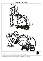
Page 8: ...stop position in a flat surface area put on the brake and turn the key into position 0 Unblock the tank by means of the two levers pos 1 placed on both sides REACH THE DRIVER S POSITION AND LIFT THE TANK BY THE GRIPS POS 2 PAYING ATTENTION TO HANDLE IT WITH CARE WHILE PUTTING IT DOWN ON THE GROUND ...

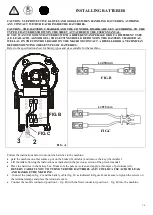
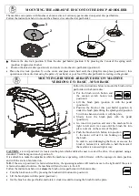
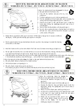
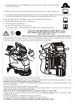
Page 9: ...zes suitable for the machine FIG C FIG B 2 3 FIG A L 250mm FIG B L 515 mm FIG C Follow the instructions below to mount the batteries to the machine park the machine on a flat surface put on the brake if available and remove the key if available Lift the tank following the instructions as indicated in the previous section of the present manual Place the batteries in the battery box Make sure the po...

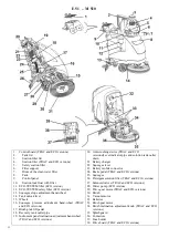
Page 10: ...t pedal 18 Recovery tank outlet pipe 19 Instrument panel inclination adjustment hand wheel TRAC and ECO versions 20 Anti crushing device TRAC and ECO versions Level indicator pipe and solution tank outlet drain 21 Battery charger 22 Squeegee lever 23 Battery mobile connector 24 Brake pedal TRAC and ECO versions 25 Squeegee 26 Detergent solution filter TRAC and ECO versions 27 Solenoid valves TRAC ...

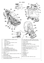
Page 11: ...CO versions 17 Brush plate lift pedal 18 Recovery tank outlet pipe 19 Instrument panel inclination adjustment hand wheel TRAC and ECO versions 20 Anti crushing device TRAC and ECO versions 21 Level indicator pipe and solution tank outlet drain 22 Battery charger 23 Squeegee lever 24 Battery mobile connector 25 Brake pedal TRAC and ECO versions 26 Squeegee 27 Detergent solution filter TRAC and ECO ...

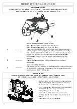
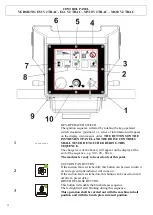
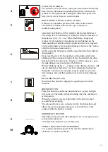
Page 12: ...WHEEL Enables the instrument panel to be positioned in three different inclinations 3 ANTI CRUSHING DEVICE This is a safety device that halts the machine in reserve drive and makes it go forward for a brief period in case the operator is trapped between the machine and an obstacle behind him BRAKE PEDAL VERSIONS E51 V2 TRAC E61 V2 TRAC M510 V2 TRAC M610 V2 TRAC E51 V3 ECO E61 V3 ECO M510 V3 ECO M6...

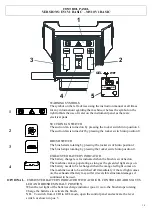
Page 13: ...rotating by pressing the rocker switch into position 0 4 EXHAUSTED BATTERY INDICATOR The battery charge level is indicated when the brush is switched on The machine can keep operating as long as the green led light stays on The battery needs to be recharged when the orange led light comes on The machine needs to be switched off immediately if the red light comes on the exhausted battery may suffer...

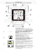
Page 14: ... will appear on the display at the end of the sequence e g 100 90 80 etc The machine is ready to be used only at this point 2 SUCTION FAN BUTTON If the suction fan is switched off this button can be used to turn it on and a green light indicator will come on If the suction fan is switched on this button can be used to turn it off after a preset delay 3 BRUSH RELEASE BUTTON This button will enable ...

Page 15: ...tion function will also be disabled the drive function will be the only active function Lift the squeegee go to the tank drainage area and charge the batteries When 4 blinking dashes appear on the display the drive will also be disabled as the battery reaches a minimum discharging threshold Therefore the machine must be pushed over to the tank drainage area and then pushed over to the battery char...

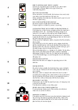
Page 16: ...ill enable the brush release sequence The led light will start blinking during this sequence This operation shall be carried out with the machine in halt position and with the brush plate in raised position 3 WATER ADJUSTMENT BUTTONS Use the buttons or to set the maximum quantity of water to use for the operation Press the button to increase the quantity of water the 5 green led lights on the pane...

Page 17: ... function Lift the squeegee go to the tank drainage area and charge the batteries When 4 blinking dashes appear on the display the machine drive will be also disabled as the battery reaches a minimum discharging threshold Therefore the machine must be pushed over to the tank drainage area and then pushed over to the battery charging area 8 HOUR METER BUTTON Hold down this button to display the ope...

Page 18: ...10 V2 TRAC M610 V3 ECO 1 2 3 There are 2 types of adjustments that can be carried out on the squeegee Inclination adjustment ALL VERSIONS with knob position 1 It adjusts the inclination of the squeegee in order to have a constant pressure over the entire length of the blade position 2 Turn the knob counter clockwise if there is too much pressure on the outer points and little pressure on the centr...

Page 19: ...ard position 5 with one hand and centre it with the plate Slowly lower the brush plate with the pedal position 1 Go into drive position and move the machine from right to left and vice versa until the brush fits into place correctly on the centre of the plate Push the brush switch button into position 1 the motor will start to run hooking on the brush In order to avoid damaging the floor as soon a...

Page 20: ...or will rotate for 2 seconds thus allowing for brush release Repeat the same operation again if necessary With the brush removed form the plate move the brush plate back into its original position by means of the knob pos 2 Turn the knob clockwise towards the sign on the label for 4 rounds inclination recommended Follow the instructions below to release the brush or disc pad holder with abrasive d...

Page 21: ...t solution suited for the type of floor and for the dirty conditions of the floor and using a product suitable for cutting down foam 1 2 3 4 Use the mouth of the tank see position 3 to fill the solution tank For TRAC and ECO versions there is a filter see position 2 located inside the mouth of the tank see position 3 which should only be removed if the opening is clogged or obstructed Use either a...

Page 22: ... before operating the machine USING THE MACHINE Our squeegee machines must be operated by properly trained authorised staff Squeegee machines that do not operate properly must be taken out of service immediately CHECK BEFORE USE Make sure to check the following before using the machine Make sure the battery connector is plugged in Make sure the key is fitted correctly Check the battery charge leve...

Page 23: ...olution is used up take the machine to the tank drainage area drain the dirty water into the appropriate location ready for disposal then wash the water tank and fill up the tank with clean water and a mix of water and detergent solution then resume the washing operation On the ECO version once the solution is used up the machine can continue its washing operation using the ECO SYSTEM function tha...

Page 24: ...st be drained and cleaned after each washing operation In order to drain and wash the tank proceed as follows Turn off the brush function and lift the brush plate Lift the squeegee by pressing the special lever and go to the tank drainage area with the suction fan in on position Turn off the suction fan turn the key to position 0 for the versions provided with a key and put on the brake if availab...

Page 25: ... duct see position 10 then let the water flow without removing the drain pipe This will help prevent encrustation formation inside the duct providing an optimal vacuum operation at all times Avoid splashing water onto the instrument panel see position 9 while cleaning the tank CLEANING INSTRUCTIONS ECO SYSTEM FOR VERSIONS E51 V3 ECO E51 V3 ECO M510 V3 ECO M610 V3 ECO At the end of each working day...

Page 26: ...IC version so the pipe must be drained towards the rear part of the machine Once the tank is drained put the cap back into the pipe and place it into its special housing hooking it back into the knob see position 1 The filter located in the mouth of the tank used for filling clean water should be cleaned periodically It is also recommended to flush the tank periodically using water once it is drai...

Page 27: ...lly see position 2 Remove the protective screen see position 3 and clean it with water together with the cup Put the cup see position 2 and the protective screen see position 3 on the fixed part of the filter see position 4 make sure the protective screen is fitted correctly into its housing inside the cup and into the support For the V2 TRAC version open the valve see position 1 or the lever hand...

Page 28: ...cuum flow remove any pieces or incrustations from the lower part and from the mouth of the squeegee see position 8 Use a piece of cloth to wipe off the rear drying blade see position 6 and the front drying blade see position 7 Make sure the blades are in good condition and rotate them if necessary in order to have a new edge in contact with the floor REPLACING SQUEEGEE BLADES FOR VERSIONS E51 V1 B...

Page 29: ...driver see position 2 and remove the 6 screws see position 3 and the respective washers see position 4 Remove the blade locking plate see position 5 Remove the blade see position 6 Rotate the blade and mount it back so that a new edge is on the drying side of the blade Put the blade locking plate see position 5 back into place Put the 6 screws back into place see position 3 including the respectiv...

Page 30: ... filter into a vertical position and pull it vigorously until releasing the filter from its housing see position 4 Wash the filter with water and dry it using hot air be careful not to damage it There is a safety filter see position 5 located beneath the suction filter which normally does not need any maintenance However if deemed necessary clean the filter without removing it from its housing Put...

Page 31: ...this switchboard BRUSH MOTOR PROTECTION FUSE HOLDER SHOWN IN POSITION 6 SUCTION MOTOR PROTECTION FUSE HOLDER SHOWN IN POSITION 1 REPLACING THE BRUSH MOTOR FUSE Pull the fuse holder lid see position 6 towards the direction indicated by the arrow and open it Unscrew the 2 locking nuts see position 4 that hold the fuse Replace the 30 A fuse see position 5 with a fuse of equal amperage Screw the nuts ...

Page 32: ...emove the switchboard cover see position 11 Remove the lid see position 8 from the fuse holder see position 7 There are 5 fuses located in the fuse holder and they have the following functions and features POSITION 1 5A fuse for electrical equipment protection POSITION 2 7 5A fuse for pump protection ONLY FOR VERSION V3 ECO POSITION 3 30A fuse for suction motor protection POSITION 4 30A fuse for d...

Page 33: ...he gearing area located inside the instrument panel Put the washer and screws back into place see position 2 and close the panel using the special wrench see position 1 make sure to apply enough pressure on the seal beneath the panel see position 4 CHECK THE SEAL ON THE COVER FOR VERSIONS E51 V1 BASIC E51 V2 TRAC E51 V3 ECO E61 V1 BASIC E51 V2 TRAC E51 V3 ECO M510 V1 BASIC M510 V2 TRAC M510 V3 ECO...

Page 34: ... RED light position 3 YELLOW light position 4 GREEN light These lights indicate the charging status of the battery The GREEN light indicates that the charging cycle is completed and the plug can be disconnected from the electrical socket and rolled back into the cable reel Once the battery is charged make sure to check the electrolyte level and if necessary fill it up only using distilled water Th...

Page 35: ...36 DIMENSIONAL DRAWINGS VERSIONS E51 M510 DIMENSIONAL DRAWINGS VERSIONS E61 M610 ...

Page 36: ...37 RECOMMENDED SPARE PARTS USED FOR SERVICING SERVICING OPERATIONS CAN BE CARRIED OUT BY THE USER HIMSELF ON CONDITON IT HAS PREVIOUSLY BEEN INSTRUCTED BY EITHER THE MACHINE OWNER OR HIS EMPLOYER ...

Page 37: ...S V1 BASE COD 520077 PPL BRUSH 0 9 mm 1 FOR EACH MACHINE COD 520078 TYNEX BRUSH 1 2 mm 1 FOR EACH MACHINE COD 520079 PAD WITH DISC LOCK 1 FOR EACH MACHINE COD 520080 PPL BRUSH 0 6 mm 2 FOR EACH MACHINE COD 520081 TYNEX BRUSH 1 2 mm 2 FOR EACH MACHINE COD 520082 PAD WITH DISC LOCK 2 FOR EACH MACHINE COD 520084 DISC LOCK COD 900617 CARTRIDGE SUCTION FILTER CLASS M exUSGC COD 900622 SELF LEVELLING SP...

Page 38: ...MP V Watt 24 120 V Watt 24 120 VACUUM MOTOR V Watt 24 480 V Watt 24 480 V Watt 24 480 V Watt 24 480 V Watt 24 480 NEGATIVE PRESSURE VACUUM MOTOR mm H2O 1250 mm H2O 1250 mm H2O 1250 mm H2O 1250 mm H2O 1250 DRIVE MECHANICAL ELECTRONIC ELECTRONIC ELECTRONIC ELECTRONIC DRIVE MOTOR WITH DIFFERENTIAL V Watt 24 180 V Watt 24 180 V Watt 24 180 V Watt 24 180 POLYURETHANE FRONT WHEEL WITH BRAKE Ø 200 X 50 Ø...

Page 39: ... of floor 20 1 The battery charge level it too much low Upon reaching level 20 the number on the display shall start blinking and the brush function will be disabled Lift the brush plate and complete drying Empty the recovery tank and recharge the batteries 0 2 The battery charge level it too much low Upon reaching level 10 the number on the display shall start blinking and the suction function wi...

Page 40: ...Replace it The drive does not work VERSIONS TRAC and ECO 20 Brake is engaged 21 Flat or worn out battery 22 Key disconnected 23 30A Fuse POS 4 OF THE FUSE HOLDER Traction fuse is faulty 24 5A protection traction fuse PSO 5 OF THE FUSE HOLDER is broken 25 Motorreducer is faulty 26 Motor carbons are worn out 27 Electronic control board is broken 28 Microswitch in the control panel is broken 29 Main ...

Page 41: ... Faulty vacuum pipe 45 Dirty squeegee 46 The squeegee is not adjusted properly 47 Material tangled with the squeegee blades 48 Squeegee blades either broken or worn out 49 The tank is either open or not properly closed 50 Damaged lid gasket 51 Faulty suction motor 52 Flat batteries Empty it Switch off the vacuum motor and unblock the float ball Tight the lid Verify that it is mounted properly Clea...

Page 42: ...to the machine and or parts which have been repaired or altered outside Eureka s plant or the facility of Eureka s Authorized Sales Service Representative This warranty does not apply to routine wearable parts such as brushes splashguards flaps filters seals plugs hoses fuses or similar items Moreover this warranty does not extend to the machine or any of its parts already repaired or replaced und...

Page 43: ...NSTALLATION DATE GENERAL INFORMATIONI 1 HAS THE LEAD TIME BEEN RESPECTED 4 HAVE YOU READ THE OPERATION MANUAL PRIOR TO USE THE MACHINE 2 HAVE YOU BEEN SHOWN HOW TO USE THE MACHINE 5 HAVE YOU BEEN OFFERED A PREVENTIVE MAINTENANCE CONTRACT 3 HAVE YOU CHECKED THE PERFECT FUNCTIONING OF THE MACHINE PRIOR TO USE IT 6 HAVE YOU ACCEPTED IT USER S INFORMATION COMPANY NAME ADDRESS N CITY PROVINCE COUNTRY P...

Page 44: ...Spazi minimi per evitare lo schiacciamento di parti del corpo UNI EN 349 Sicurezza degli apparecchi elettrici d uso domestico e similare Parte generale EN 60335 1 1994 A11 1995 A1 1996 A2 2000 A13 1998 A14 1998 A15 2000 A16 2001 Sicurezza degli apparecchi elettrici d uso domestico e similare Parte 2 Norma particolare per macchine automatiche per il trattamento dei pavimenti per uso industriale e c...

Reviews: