background image

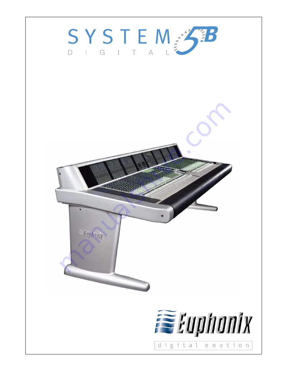
Digital Audio Mixing System

Operation Manual

Document Revision

: 1.1

Release Date

: August, 2005

eMix version

: 2.8.1

Part Number

: 840-09147-01

Euphonix, Inc.

220 Portage Ave.
Palo Alto, California 94306
Phone: 650-855-0400
Fax: 650-855-0410
Web:

http://www.euphonix.com

e-mail: [email protected]

Summary of Contents for System 5B

Page 1: ...anual Document Revision 1 1 Release Date August 2005 eMix version 2 8 1 Part Number 840 09147 01 Euphonix Inc 220 Portage Ave Palo Alto California 94306 Phone 650 855 0400 Fax 650 855 0410 Web http ww...

Page 2: ...n by Rob Wenig Manual written by Tim Driedger and Rob Wenig Note This equipment has been tested and found to comply with the limits for a Class A digital device pursuant to Part 15 of the FCC Rules Th...

Page 3: ...r s instructions 8 Do not install near any heat sources such as radiators heat registers stoves or other apparatus including amplifiers that produce heat 9 Do not defeat the safety purpose of the pola...

Page 4: ...r supply cord shall remain readily operable 19 This unit is provided with a power supply cord set suitable for 120V AC input only for U S A and Canada For other than U S A and Canada a qualified perso...

Page 5: ...1 4 System 5 B Startup Sequence 22 Chapter 2 New Features in Version 2 8 1 23 Chapter 3 Quickstart to Common Task 25 3 1 Connect and Play a CD 25 3 2 Connect and Monitor a Microphone 28 Chapter 4 eMix...

Page 6: ...1 Monitoring 56 5 1 1 Monitor Source Selection 57 5 1 2 Main Section and Aux Send Format 58 5 1 3 Control Room Monitor Controls 58 5 1 4 SLS Cue Monitor Outputs 60 5 2 Communications 61 5 2 1 Talkback...

Page 7: ...Section 80 Chapter 7 Busses and Bus Masters 81 7 1 Introduction to System 5 B Busses 81 7 2 Bus Master Functions 82 7 2 1 Aux Grp and Main Masters 83 7 2 2 Bus Lock 83 7 2 3 Mon Lock 83 7 2 4 All Key...

Page 8: ...8 2 7 Talk 100 8 2 8 Copy and Paste 100 8 3 Channel Processing Functions 101 8 3 1 Inputs 101 8 3 2 Dynamics 104 8 3 3 Equalizers and Filters 107 8 3 4 Aux Sends 109 8 3 5 Pan 111 8 4 Channel Process...

Page 9: ...ame a Layout 132 10 1 5 Delete a Layout 133 10 2 Snapshots 133 10 2 1 Create a New Snapshot 133 10 2 2 Recall a Snapshot 135 10 2 3 Update Snapshot 135 10 2 4 Rename a Snapshot 136 10 2 5 Delete a Sna...

Page 10: ...3 Move a Fader to Start a Cart Machine 145 11 9 4 Move a Fader to Stop a Cart Machine 146 11 9 5 Video Switcher Turns a Specific Camera and Channel On 147 11 9 6 Video Switcher Turns a Specific Camer...

Page 11: ...nputs normalled 37 4 7 Simplified MADI routing diagram 39 4 8 Console I O A and B inputs Window 40 4 9 Bottom of Console I O window 41 4 10 Device Outputs window 43 4 11 Selecting destination channels...

Page 12: ...ol Panel 79 6 5 Bus Routing Panel 80 7 1 CM401 Center Section with Bus Master Strip 82 7 2 Main Bus Master left and Individual Bus right Displays 84 7 3 Aux Bus Settings 85 8 1 The Strip with block di...

Page 13: ...20 Mix Minus Knobset and Signal Flow 121 9 1 Groups Panel 124 9 2 Masters Screen 126 10 1 Layouts Panel 131 10 2 Snapshots Panel 134 11 1 Event Configuration Window 141 11 2 Add Input Event Dialog 14...

Page 14: ...System 5 B Digital Audio Mixing System Operation Manual xiv...

Page 15: ...f Tables 4 1 Monitor Bussses 47 4 2 Law Palette Formats 49 6 1 Center Panel Knobset Presets 79 11 1 GP Input Types Settings and Activation Values 138 11 2 GP Output Types Settings and Activation Value...

Page 16: ......

Page 17: ...ntroduction in its entirety Chapter 2 summarizes new features in this software revision The manual contains the following chapters Chapter 3 Quickstart to Common Task Provides the fastest way to begin...

Page 18: ...ow it to hover over the heading and turn into a fin ger Then click to locate to that subject and page All cross references are active links Allow the hand cursor to hover over the reference turn into...

Page 19: ...m the MADI format through analog and digital converters The System 5 B includes eight MADI Inputs and six MADI Outputs Each 75 coaxial MADI ca ble can carry up to 56 channels of 24 bit digital audio a...

Page 20: ...to MADI ML530 Analog Mic Line AM713 Analog to MADI Talk Listen Mics Speakers FC726 Digital FC726 Digital Ethernet Control MADI Analog Audio Digital Audio 24 24 24 Typical System 5 B Configuration 96...

Page 21: ...y assigning and controlling channels Channel Format Most analog consoles are limited to mono or stereo channels System 5 B supports mono and stereo channels as well as Multi Format Masters LCRS 5 1 6...

Page 22: ...es appear as Unexpected the user can select all of the modules by holding down the Ctrl key and clicking each of them When all modules are selected click Save selected as default and confirm the selec...

Page 23: ...send parameters unity pre post fader on off stereo mono can now be quickly set for multiple Aux sends Level settings can be copied from Faders to Aux and from Aux to Aux It is also possible to control...

Page 24: ...System 5 B Digital Audio Mixing System Operation Manual New Features in Version 2 8 1 24...

Page 25: ...like Save As click Reset Console with Default Title settings to use default Title settings Figure 3 1 New Title dialog Assign Channels to Console 1 Select Channels from the main panel viewer in the co...

Page 26: ...the Name column for channel 1 and name the device CD Player Left click in the Name column for channel 2 and name it CD Player Right 7 Click the green selection fields next to channels 1 and 2 to add t...

Page 27: ...or the B Mix Bus defaults to stereo 4 In the Master Section press the CR Source key to display the Mix sections in the Panel Viewer Select the B Source 5 Move the channel 1 and 2 faders up 6 Press bot...

Page 28: ...L530 is connected 4 Click Patch Figure 3 3 Cabling Assign a Channel to the Console 1 Select Channels from the Main Panel Viewer 2 Select Auto then Channel 3 3 Press the Chan Sel key on a Strip 4 Press...

Page 29: ...art to Common Task 29 4 Select the green selection box for Mic Line 1 Ch 1 and name the channel The patch point shows up in Selected Destinations 5 Click Patch The knobs on Channel 3 now display HiZ 4...

Page 30: ...he B Mix bus 3 In the Master Section press the CR Source key to display the Mix sections in the Panel Viewer and select the B Source 4 Activate channel 3 s ON switch move its fader up and set the Pan...

Page 31: ...em status Each tab is discussed in the following sections 4 1 Directory The Directory tab contains its own tabs right above the main eMix tabs Drives Projects Titles and Mixes The order of these tabs...

Page 32: ...ck the Projects tab or double click the Drive The Projects Window appears with a list of Projects on that Drive 3 To create a new Project click the New button along the right side of the Projects wind...

Page 33: ...button is used Click the Paste button to paste the copied Project Of course you can navigate the Directory to another Drive before pasting If the selected Project s name is Test the copied Project is...

Page 34: ...le click the Project The Titles Window appears with all Titles in that Project 4 Click the New button along the right side of the Titles window The New Title dialog appears Figure 4 3 New Title dialog...

Page 35: ...ct 4 To open the Title select the Title and click Open 4 1 3 Operations on Current Title Figure 4 4 File operations buttons for current Title The two buttons at the top of each Directory Window provid...

Page 36: ...an the System 5 B console Therefore Device In puts refers to inputs to an external device not the console The following settings are stored to the Title Defaults and are automatically included with ea...

Page 37: ...1 and DAW inputs Figure 4 6 shows the Group Bus outputs patched to the R 1 inputs If a Source is normalled to multiple destinations i e R 1 and DAW MULT ap pears in the blue cell next to the source n...

Page 38: ...ured and stored as presets so they appear in their most useful formats See Meters on page 70 for more information The following are useful meter presets All meters single follow fader All meters singl...

Page 39: ...the Sony 3348HR recorder and some high end consoles offer a MADI interface Most other equipment however i e mics speakers DAWs that support AES EBU and vintage gear must have their inputs and outputs...

Page 40: ...tion is stored in the Title Default so these settings can be used when starting a new session with a new Title To set up the System 5 B studio wiring and set the Title Default see Title Defaults on pa...

Page 41: ...O window 4 2 2 Device Inputs and Outputs There are up to 12 MADI device input output ports on the console each carrying up to 56 channels 44 1 48 kHz or 28 channels 96 kHz NOTE To clarify the use of...

Page 42: ...I In Ports sub category 5 Click and drag through the cells to the right of the two Hub1 inputs Hub1 1 and Hub1 2 The cells highlight and the names appear in the Destinations column of the Se lected wi...

Page 43: ...ighted in green in Figure 4 10 These sources appear in the Sources column of the Selected window below If there were more than 24 sources additional tabs would appear to the right of the 1 24 tab Sele...

Page 44: ...xt to C25 C36 to select channels 25 36 The entries are highlighted in blue and the list of A input channels appear in the Destinations column in the Selected window below Figure 4 11 Figure 4 11 Selec...

Page 45: ...s appear in the Sources col umn in the Selected window below 4 Select the Console I O category 5 Select the A and B Inputs sub category 6 Click and drag through the first 24 cells in the A Input colum...

Page 46: ...main section are routed to channels 41 46 A inputs The insert is switched in out from the Bus Masters Config Page see Bus Master Inserts on page 88 Figure 4 14 Main Bus Send and Return graphic For ev...

Page 47: ...ching into the stereo Solo Bus The Utility Sources sub category includes the Oscillator output The Utility Destina tions sub category includes the Slate In which must be patched to the Talkback mic fe...

Page 48: ...click either the Group or Main buttons to configure the Group or Main sections respectively Figure 4 15 shows the Main sections Figure 4 16 shows Group sections Group busses and Main sections differ...

Page 49: ...law for a Main section 1 Click and drag across the busses you wish to configure 2 Right click on any of the selected cells to display the Law Palette Figure 4 17 Law Palette The possible formats are...

Page 50: ...k the Masters tab at the bottom of the eMix window At the bottom left of the win dow click the Externals button to configure the Externals Externals are configured in the same way as Main and Group bu...

Page 51: ...apped to some channel s in the Format Out However this is not mandatory One might choose to omit the Boom channel because the speakers in the output format cannot handle bass below a certain frequency...

Page 52: ...user to inspect the Diagnostics page Display the Diagnostics page by clicking the Euphonix logo at the bottom left corner of the main Emix screen Press the reset button on the module DSP card or PC th...

Page 53: ...plication 53 4 8 Masters See Chapter 7 Busses and Bus Masters 4 9 Events See Chapter 11 GPI O Event System 4 10 System 5 Logo Clicking on the System 5 Logo in the lower right corner of the eMix screen...

Page 54: ...System 5 B Digital Audio Mixing System Operation Manual eMix Application 54...

Page 55: ...0 54 48 42 Main Monitor Comms Talk Listen Slate Osc R W H T Y N Copy Paste Func Select SEL IN SEL IN SEL IN SEL IN SEL IN SEL IN SEL IN SEL IN Y X L C R Sl Sr B LR phase Chan Select Talk Swap Solo ON...

Page 56: ...5 2 Monitoring Matrix Source selection for the monitor output can either intercancel only one source to a monitor output or sum multiple sources The Control Room monitor outputs can be folded down fr...

Page 57: ...ailable sources within that type appear in the Panel Press a key along the sides of the Panel to select a source The active source key lights and the name appears in the LCD display above the Mon A D...

Page 58: ...til a new source is explicitly selected Follow Control Room Monitors Activate the FlwCR key so the Mon A D outputs follow the source selected for the Control Room monitors 5 1 2 Main Section and Aux S...

Page 59: ...ut level knob s center switch or the Cut switch Monitors A D may be switched off on by pressing the output level knob s center switch they are off when their output level knob s center LED is not lit...

Page 60: ...edicated level knob and output level LCD display see Figure 5 4 The knob LEDs also indicate the current level CR Speakers There are three speaker outputs within the Control Room Monitors Main 7 1 Alt1...

Page 61: ...encies at 100 Hz 440 Hz 1 kHz 10 kHz and a user selectable frequency The oscillator can also generate pink or white noise The oscillator can be routed to the Group Aux or Main sections or to all busse...

Page 62: ...e Main CR speaker and the monitors receiving talkback are dimmed by the level set for the DIM key see Dim and Cut on page 59 Set the Tbk1 level by activating the Tbk1 xx x key and using the soft keys...

Page 63: ...ack Press the Lsn key at the bottom of the Comms Talkback Panel to display the Comms Listenback Panel Figure 5 6 Figure 5 6 Comms Listenback Panel Main Panel Info Comms Listenback Lsn Flw 4 Lsn 1 Lsn...

Page 64: ...ms Talkback Panel to display the Comms Slate Osc Panel Figure 5 7 Turn the oscillator on by activating the Osc On key Select the oscillator type by press ing the Osc Sine Osc White or Osc Pink keys on...

Page 65: ...c 1kHz Osc 10kHz Osc Grp Osc Mix Osc Pink Slt 20 0 Slt Grp Slt Mix Slt ALL Osc White Oscillator frequencies User settable Oscillator frequency Oscillator wave types Slate frequency Slate Bus assignmen...

Page 66: ...isplay Quick Access Panels for general Communi cations Talkback Listen and Slate Osc Figure 5 8 Figure 5 8 Quick Access Communication Panels ON Y X L C R Sl Sr B Control Room Comms T alk Listen Slate...

Page 67: ...mode APL After Pan Listen Signal is post fader and pan stereo PFL Pre Fader Listen Signal is pre fader in mono SIP Solo In Place Allows soloed channels through to the main busses Mutes all chan nels...

Page 68: ...keys Soled channels must then be explicitly cleared There are two other options available in the Solo Control Panel that control the Solo key Momentary The Solo key must be held down but multiple cha...

Page 69: ...made Solo Safe The chan nel s Solo key also lights dimly when in Solo safe mode 3 Press additional Chan Select keys 4 Press the Solo Safe key again or another Solo Control Panel key to exit the mode 5...

Page 70: ...to display two meters to track different information When displaying one meter the dynamics gain reduction is shown to the right of the channel meter Figure 5 10 Group Main Aux Any Group Main or Aux...

Page 71: ...etc along the right side and the arrows appear opposite Group Each Strip can have a different meter configuration but it is also easy to assign the same configuration to consecutive Strips with automa...

Page 72: ...Meter measures the Swap channel even when Main is active Ch Meter measures the assigned channel even if it is not assigned to that Strip NOTE It is most common to meter the Fader Main or Swap signals...

Page 73: ...er section meters showing 5 1 channel CR and Aux Busses 1 8 The TFT screen above the center section shows two meters one above another The up per meter automatically shows the selected monitor output...

Page 74: ...System 5 B Digital Audio Mixing System Operation Manual CM401 Master Section 74...

Page 75: ...on the knobsets Dynamics and EQ knobsets The Center Strip channel s dynamics and EQ are always displayed on these knobsets Channel Select Panel Assigns a channel to the Center Strip Eight assignable S...

Page 76: ...ON ON ON ON ON ON ON ON ON ON ON ON ON ON ON ON ON ON ON ON ON ON ON ON ON ON ON ON ON ON ON ON Knob Values Slct Punch Slct Punch cfg cfg solo solo solo solo solo solo solo solo solo solo solo solo so...

Page 77: ...t and the name key not lit The Group key toggles between displaying channels key not lit and Control Groups key is lit The global ON and Solo keys on the bottom of the panel determine whether the left...

Page 78: ...6 2 1 Knobset Control Panel The Knobset Control Panel configures the knobs above the panel and which pages of Dynamics and EQ appear below it The Input and Aux functions have configu ration pages whic...

Page 79: ...LCD displays show the selected functions The bottom two LCD displays are fixed at Dynamics and EQ Table 6 1 Center Panel Knobset Presets The Slct Punch switch selects it for inclusion when a Snapshot...

Page 80: ...ches light to show that the Center Strip channel is routed to that Group Bus 6 3 2 Main Route When the Main Route key is lit all 48 switches indicate Main Bus routing The green number LEDs light to in...

Page 81: ...any format Main Busses also have playback returns Aux and Group busses do not Group Busses Group busses are used to route channels to multitrack recorders DAWs mix minus feeds and sub groups Group Bu...

Page 82: ...Main Monitor Comms Talk Listen Slate Osc R W H T Y N Copy Paste Func Select SEL IN SEL IN SEL IN SEL IN SEL IN SEL IN SEL IN SEL IN Y X L C R Sl Sr B LR phase Chan Select Talk Swap Solo ON ON Aux EQ...

Page 83: ...Lock The Mon Lock key disables adjustment of the Control Room Monitor levels Dim and Cut always remain active See Monitoring on page 56 for more information on monitor controls 7 2 4 All Key The All k...

Page 84: ...evel of that Main section Press a knob to display individual section meters on the TFT screen Press the lower of the two buttons to the left of each knob to turn that Main sec tion On Off All individu...

Page 85: ...splay the first eight Group or Aux Bus Masters Use the W and X keys to display additional busses The knobs control the bus levels and the lower button to the left of the knob turns that bus on off See...

Page 86: ...elected Aux busses can now be toggled on off from this panel 1 Press the On Off button 2 Press the desired Aux bus knob s 3 When finished select a different Aux function This effects only those channe...

Page 87: ...1 Press the Aux Copy button 2 Press the Aux bus knob from which the settings are to be copied 3 Press the Aux bus knob to which the copied settings are to be pasted 4 When finished select other Aux bu...

Page 88: ...sert in out works the same for Aux Main and Group busses 1 Press the Aux Mstrs Grp Mstrs or Main Mstrs button to display that bus on the Bus Master knobset 2 Press both cfg W and X keys simultaneously...

Page 89: ...s the channel Any channel can be assigned to any Strip assignments need not be consecutive Two Strips can control one channel allowing two users to simultaneously oper ate that channel Channels with r...

Page 90: ...ds Group Busses Matrix Clean Feeds Main Busses Program Sub Groups System Buses Channel Output Mix Minus Output Fader Mute Any Order Insert Function 3 of 7 Function 2 of 7 Delay DYN Pan Pan Key Link Tr...

Page 91: ...desired channel 2 Press and hold down the Wave key and press the Chan Select key The channel list appears on the meter bridge screen at the top of the Strip Control Groups that have been created also...

Page 92: ...e Channel Assign Panel Use the Page keys to display additional channels Figure 8 3 Channel Assign Panel 3 In the Channel Assign Panel Viewer press the key beside the channel you wish to assign 4 Activ...

Page 93: ...ross to the Swap key of the same Strip 6 Continue sliding your finger to the right over the Chan Select and Swap keys of each Strip until you have pressed the Swap key on the last Strip you wish to as...

Page 94: ...Fader Unity and Fader Meters Figure 8 4 Figure 8 4 Strip Config panel Main Panel Page 2 Info Fader Text 402 Fader Text Knob Text Momentary Values Always Show Values Always Show Text Momentary Values...

Page 95: ...e key again to unlock it The TFT display shows Locked above that Strip Strip Expand Strip Expand expands the display and control of a single Strip over several Strips per mitting easier access to knob...

Page 96: ...the Fader Unity key so it lights 3 Press the Chan Select key for each channel to set unity gain The fader moves to 0 dB You can also press that channel s Channel Select key in the center section Selec...

Page 97: ...ction has more than eight parameters the WX keys above key page backward and forward to display the additional settings Four function in out switches are located to the left of the function selection...

Page 98: ...switch for inclusion in a Snap shot and pages to a second knob function if it exists Each knob has a center switch that selects that knob for inclusion in a Snapshot Tapping the knob switch shows the...

Page 99: ...Center Section Press the Wave key when selecting Strips and channels for Layouts Strip Expand Strip Lock or other operations Like a shift key the Wave key modifies other keys See 8 2 8 for example 8 2...

Page 100: ...the Copy key flashes 2 Press the Func Select key to the left of the key to copy the knobset function currently assigned to the knobs to the copy buffer Other functions can be add ed to the buffer by p...

Page 101: ...or monitor inputs Channel 1A is from the Group 1 Bus output while 1B is from the recorder s track 1 output The A B source switch then acts as a bus tape switch Press the Input function key to display...

Page 102: ...knob controls the analog input gain Spin the knob to adjust the gain between 12 and 72 dB NOTE If an ML530 Mic Line Interface is not patched to the input the top four knobs are blank Digital Controls...

Page 103: ...ore of the left channel rotate right to hear more of their right channel Rotate left or right until the display reads 100L or 100R to hear only the left or right channel Left to mono Press the upper k...

Page 104: ...r 8 3 2 Dynamics Each channel has a compressor expander gate with an external key input Press the Dyn function key to assign Dynamics to the knobset the TFT display at the top of the Strip shows the d...

Page 105: ...ys display other Dynamics pages Expander In Out Expander Gate page 2 Compressor Limiter page 1 Depth dB Release time ms Attack time ms Threshold dB Infinity 1 Gate Infinity 1 Hard Limiter Ratio cfg cG...

Page 106: ...Compressor threshold dB cRat ratio infinity 1 hard limiter The lower switch next to the cRat knob switches the compressor in out Expander Gate xDpt expander depth limits the maximum gain reduction in...

Page 107: ...EQ func tion switch to display the EQ controls on the knobset Press the X key to display the Filters page Figure 8 11 Figure 8 11 EQ and Filters knobsets HiF HiG HmF HmG LmF LmG LoF LoG HiQ Page keys...

Page 108: ...turned clockwise boost the level is indicated by a bright LED The LEDs light for every change of 2 dB Q can be adjusted in the range 0 2 12 higher number corresponds to narrower band width At a given...

Page 109: ...hich temporarily changes the filter to band pass by pressing the Listen key next to the frequency knob The listen setting is not saved in the Title and is not automated Listen defaults to Off 8 3 4 Au...

Page 110: ...config pages cfg 1 2 3 4 5 6 Pan Pan 7 8 Press a page key to display additional Aux Send pages Aux Send Knobset Aux 1 2 Gain on off on off Aux 3 Gain in out on off Aux 1 2 Pan Aux 7 8 Gain Aux 7 8 Pa...

Page 111: ...function key to assign the Pan parameters to the knobset Figure 8 13 See Section 8 5 1 Group Bus Routing and or Section 8 5 2 Main Bus Routing to re view how to use the Pan to switch to insert Pan Fi...

Page 112: ...tiple channels the signal moves from channel one into two and then begins crossfading into channel three before channel one has completely faded out This results in smoother dynami cally panned object...

Page 113: ...nything to the center main bus SmartPan automatically uses a stereo pan law so the signal is still present when panned to the center SmartPan is always on and cannot be disabled by the user Track Pann...

Page 114: ...processor order and patch points To display the configuration controls for processor order and patch points 1 Press the Input function key to assign the Input controls to the knobs 2 Press both cfg WX...

Page 115: ...uts another inputs from a digital multitrack machine 3 When the desired group is located use the knob to scroll the list to highlight the correct input 4 Press the knob switch to select that input 5 E...

Page 116: ...t to the Channel On key to abort the selection 8 4 3 Insert Point Each channel can have an insert point with a send and return that can be patched with PatchNet The insert point can be anywhere among...

Page 117: ...the display shows only four characters Group 11 12 is displayed as 11 2 Figure 8 17 GRP and MAIN route switches The upper switch to the left of each knob assigns the first of the two Groups in the di...

Page 118: ...usts the master level for all Group busses Last Page Page 1 on off cfg Copy Paste GSL Pre Bus Mix cfg Copy Paste 1 2 3 4 5 6 7 8 9 1 0 1 1 2 1 3 4 1 5 6 Page key back to group bus assign assign enable...

Page 119: ...CM401 master section has bus master functions see Chapter 7 Busses and Bus Masters Route a Channel to a Main Section Figure 8 19 Main Section Routing Knobset Main Sections Main Busses Expand Section...

Page 120: ...the Pan to key to switch Pan in out for the Main sections This key is active only when accessing the Main or Group Bus routing pages The key lights dimly in other modes to show that Pan is active in...

Page 121: ...s Output Post Processing Pre Fader Mix Minus Processing On Off On Talk Switch Subtract Gain From Mix Minus Ref Bus To Mix Minus Ref Bus From Talkback Mic Bus Switch Off On Off Mix Switch Off On Pre Sw...

Page 122: ...back mic to the MC524 s Talkback 1 input 2 Physically connect the MC524 s Talkback 1 output to a spare A D input on an AM713 3 In the Patch view patch the A D Source into the Utility Destinations Slat...

Page 123: ...r fader can be used to change the fader level of all announcer mics System 5 B allows up to 48 Control Groups each of which can control the following channel settings Fader On Off Pan Aux Filters EQ D...

Page 124: ...trol Groups and Multi Format Masters 124 Figure 9 1 Groups Panel Main Panel Info Groups Strg Vox G5 Drms Guit G6 G7 G8 G9 G10 G11 G12 New Mod Clr Name Create New Group Clear Group Modify Group Rename...

Page 125: ...Groups appear in the list when assigning a channel see Section 8 1 1 Map Channels and Con trol Groups to Strips The Master LED lights when a Control Group is assigned to a channel 9 1 3 Modify Contro...

Page 126: ...5 1 6 1 and 7 1 channels to be built from mono channels The Multi Format Master channel can be assigned to a Strip just like a normal channel There can be up to 48 Multi Format Master channels The mos...

Page 127: ...n Panel 2 Select a master channel and assign it to a Strip All Multi Format channels have a pan width control activated by the upper switch to the left of the PanF knob Multi Format masters can be aut...

Page 128: ...the slave when the Control Group was created or subsequently For example adjusting EQ on a Control Group master has no effect on the slave channel unless the slave channel s EQ is switched in If a VT...

Page 129: ...channel to strip mapping For example channel 8 is mapped to Strip 3 Main level Snapshots store the settings of selected channel functions and settings even if they are not currently assigned to the c...

Page 130: ...are normally required on the con sole at the same time i e drums vocals or dialogue are ideally stored in a Layout The Layouts Panel provides the interface to name store modify and recall up to 48 ch...

Page 131: ...anel Unused locations are darkened and have a default name L In Figure 10 1 the first unused location is L 13 The New key darkens and the Name key illuminates 5 Use the console keyboard to name the ne...

Page 132: ...1 Press the Mod key at the bottom of the Layout Panel so it flashes 2 Press the key corresponding to the Layout you wish to modify The key begins flashing and the Wave keys for Strips in this Layout i...

Page 133: ...5 B s pre defined memory area depends on the content of each Snapshot There are 240 storage locations but only a fraction of these can be used in the largest console configuration with all settings s...

Page 134: ...Main and Swap channels currently on the surface Or All Functions in All Channels in Mixer Model Press the ALL key at the bottom right of the Snapshot Panel to select all Knobset functions in all cons...

Page 135: ...difying a Snapshot 10 2 2 Recall a Snapshot To recall a single Snapshot 1 If the RCL key is not lit press it once so it begins flashing 2 Press the key corresponding to the Snapshot you wish to recall...

Page 136: ...e keyboard to rename the Snapshot eight characters maximum 4 Press the Enter key on the keyboard the Snapshot s key or Name key again to store the new name and exit the process 10 2 5 Delete a Snapsho...

Page 137: ...channel on fader etc or external inputs via the GP132 Outputs can be System 5 B parameters or exter nal outputs via the GP132 GP132 The GP132 General Purpose Input Output Relay System is used to commu...

Page 138: ...ues Input Type Settings Activation Values Control Room Monitor A Monitor B Monitor C Monitor D Control Room Cut Control Room Dim On Off Fader Channel Activation Level dB Activation Type Above Below GP...

Page 139: ...alues Control Room Monitor A Monitor B Monitor C Monitor D Control Room Cut Control Room Dim On Off GP Output Relay Output 1 32 Pulse length ms 0 to latch 0 to 1000 ms Machine GP132 One GP132 Two GP13...

Page 140: ...ent Configuration Display Access the Events configuration screen by clicking the Events tab at the bottom of the eMix screen The Events screen has three sections Inputs Event List and Outputs Several...

Page 141: ...click to add event field at the bottom of the Description column Click in the Description field to type a description Select the logical operator from the Logic dropdown menu 11 6 Input The input are...

Page 142: ...ut output type Modify the settings by clicking on the dropdown menu and or edit display 11 7 Output The output area has two sections The top contains a list of output actions for all events in the Eve...

Page 143: ...ration window under Event List click on the click to add event field The Add Event dialog appears 2 Select Or as the logical operator from the dropdown menu 3 Under Input click on the click to add inp...

Page 144: ...ropdown menu 3 Under Input click on the click to add input field The Add Input Event dialog appears 4 Select Fader from the dropdown menu and click OK 5 Configure the Input Properties to the following...

Page 145: ...ogical operator from the dropdown menu 3 Under Input click on the click to add input field The Add Input Event dialog appears 4 Select Fader from the dropdown menu and click OK 5 Configure the Input P...

Page 146: ...gical operator from the dropdown menu 3 Under Input click on the click to add input field The Add Input Event dialog appears 4 Select Fader from the dropdown menu and click OK 5 Configure the Input Pr...

Page 147: ...down menu 3 Under Input click on the click to add input field The Add Input Event dialog appears 4 Select GPI from the dropdown menu and click OK 5 Configure the Input Properties to the following sett...

Page 148: ...n menu 3 Under Input click on the click to add input field The Add Input Event dialog appears 4 Select GPI from the dropdown menu and click OK 5 Configure the Input Properties to the following setting...

Page 149: ...em 149 11 9 7 Audio Follow Video In this example there are four cameras each with a microphone configured with a video switcher GP 132 and System 5 B console Figure 11 3 Figure 11 3 Audio Follow video...

Page 150: ...audio is on while chan nels 1 3 are muted The following steps explain how to turn channel 1 on and mute the other channels when the video switcher takes camera 1 1 Choose a tally input to use on the G...

Page 151: ...er 9 Repeat Steps 6 7 to create additional output events to mute channels 2 4 but use the following settings instead of those depicted in Step 8 Figure 11 8 Output Event Properties Figure 11 8 shows C...

Page 152: ...System 5 B Digital Audio Mixing System Operation Manual GPI O Event System 152...

Page 153: ...109 Digital Controls 102 Dynamics 104 EQ and Filters 107 Inputs 101 Pan 111 Signal Processing 104 Stereo Controls 103 Clear key 68 99 CM401 Master Section 55 CM402 Center Section 75 Communications 61...

Page 154: ...78 97 L Layout 95 129 130 Level 27 30 59 63 64 112 118 Lock 94 Bus 83 Mon 83 Strip 95 M MADI 39 41 47 115 Main Bus 83 119 Main Bus Routing 119 Main Busses 81 85 Main Section 119 Meters 94 Presets 38...

Page 155: ...36 42 Slate frequency 64 level 64 Snapshot 129 133 Solo 67 APL 67 Backstop PFL 69 Busses 47 Film Mode 67 Intercancel 68 Level 68 Mode 67 Momentary 68 PFL 67 Safe 69 Speaker Dim 68 Speaker Selection 68...

Page 156: ...System 5 B Digital Audio Mixing System Operation Manual 156...

Reviews: