EUfire NC951 Design & Installation Manual Download Page 3

DESIGNING AN ACCESSIBLE TOILET ALARM SYSTEM

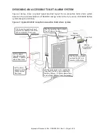
Figure  2  below,  shows  a  typical  ‘good  practice’  layout  for  an  accessible  toilet  alarm  system
based on the recommendations of BS 8300. Always refer to the full version of BS 8300 before
system design/installation.

Figure 2 : Typical BS 8300 Compliant Accessible Toilet Alarm System

WC

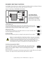
Indicators will operate: 

Continuously when pull cord is activated

Approved Document No.: DNU0951001 Rev 3 • Page 3 of 8

Site the ceiling pull so its pull
cord can be operated from the
WC and adjacent floor area.

Site the call controller
outside the WC in a
remote staffed area.

Site the reset point so it is reachable
from both the WC and a wheelchair.
Position 750mm - 1200mm above floor
level, at least 350mm from the corners.

Set the lower
triangle exactly
100mm above
floor level.

Set the upper
triangle between
800mm - 1000mm
above floor level.

4 core

security cable

230Va.c.

3A switched

fused spur.

Site the overdoor light outside
the WC above the door.

1mm

2

T&E

Summary of Contents for NC951

Page 1: ...iling Pull Includes a red reassurance LED red pull cord and two triangular pull bangles NC949 Accessible WC Sticker NC943B Single Zone Call Controller c w Sounder Includes a link selectable Call Accep...

Page 2: ...le gang back box TYPICAL LOCATION Inside the WC so it is reachable from the toilet and a wheelchair Position 750 1200mm above floor level and at least 350mm from corners DO NOT connect Ve to the ceili...

Page 3: ...Approved Document No DNU0951001 Rev 3 Page 3 of 8 Site the ceiling pull so its pull cord can be operated from the WC and adjacent floor area Site the call controller outside the WC in a remote staffe...

Page 4: ...ic back box is used make the earth connection to the earth terminal at connector block CONN2 If a metal back box is used the earth connection must be made to the earth bonding point on the back box Ex...

Page 5: ...the scope of BS 8300 and therefore not recommended for use in accessible toilet alarm installations However they may be suitable for use in other applications subject to the approval of the responsibl...

Page 6: ...out by pressing the reset point s RESET button EXPANDING THE SYSTEM WITH OPTIONAL EMERGENCY CALL LEVEL Up to three additional 800 Series devices any device mix can be connected to the NC943B call cont...

Page 7: ...larm call has been raised Outside the WC A member of staff accepts the alarm call by pressing the call controller s Call Accept button Outside the WC Once assistance has been provided the call is canc...

Page 8: ...nerates an alarm call when activated Indicator Red reassurance LED active in alarm IP Rating IP41 when correctly installed Mounting Surface mountable Dimensions 93mm diameter x 27mm deep NC806CS Overd...

Reviews: