Operating Instructions
Modular Safety Control System MSC
28
(Translation of the original operating instructions) 2121331-04-04/19
7. Signals
7.1. Inputs
7.1.1. MASTER_ENABLE
The base unit MSC-CB has two inputs: MASTER_ENABLE1 and MASTER_ENABLE2.
NOTICE
These signals must both be set permanently to logic level 1 (24 VDC) so that the MSC system functions
correctly. If you want to deactivate the MSC system, these inputs can be simply set to logic level 0
(0 VDC).
7.1.2. NODE_SEL
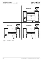
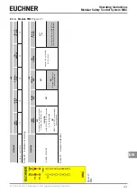
The inputs NODE_SEL0 and NODE_SEL1 (on the extension modules) are used to assign an address to the extension modules
using the connections given in Table 16:
NODE_SEL1 (TERMINAL 3)
NODE_SEL0 (TERMINAL 2)
NODE 0
0 (or not connected)
0 (or not connected)
NODE 1
0 (or not connected)
24 VDC
NODE 2
24 VDC
0 (or not connected)
NODE 3
24 VDC
24 VDC
Table 16: Node selection
A maximum of 4 addresses and therefore 4 modules of the same type are intended to be used in the same system.
NOTICE
Two modules of the same type are not allowed to be assigned the same physical address.
Summary of Contents for MSC
Page 1: ...EN Operating Instructions Installation and use Modular Safety Control System MSC ...
Page 171: ......
Page 173: ......

