


3
Operating Instructions
Precision Multiple Limit Switches GL, GS, SB, SN 8 mm
Correct use
Precision multiple limit switches are used for posi‑
tioning and controlling machines and in industrial
installations.
Correct use includes compliance with the relevant
requirements for installation and operation, in
particular
f
EN 60204‑1
f
EN ISO 12100
Incorrect use
Precision multiple limit switches with switching
elements ES 552, ES 592 and ES 614 (snap‑action
switching contacts not positively driven) must not
be used in safety circuits.
Function
Precision multiple limit switches possess several
switching elements arranged in a row.
The switching elements are actuated by means of
plungers. Different plunger types and trip dogs are
used depending on the application (operating point
accuracy and approach speed).
The plungers are actuated by trip dogs that are
mounted with an interference fit in trip rails.
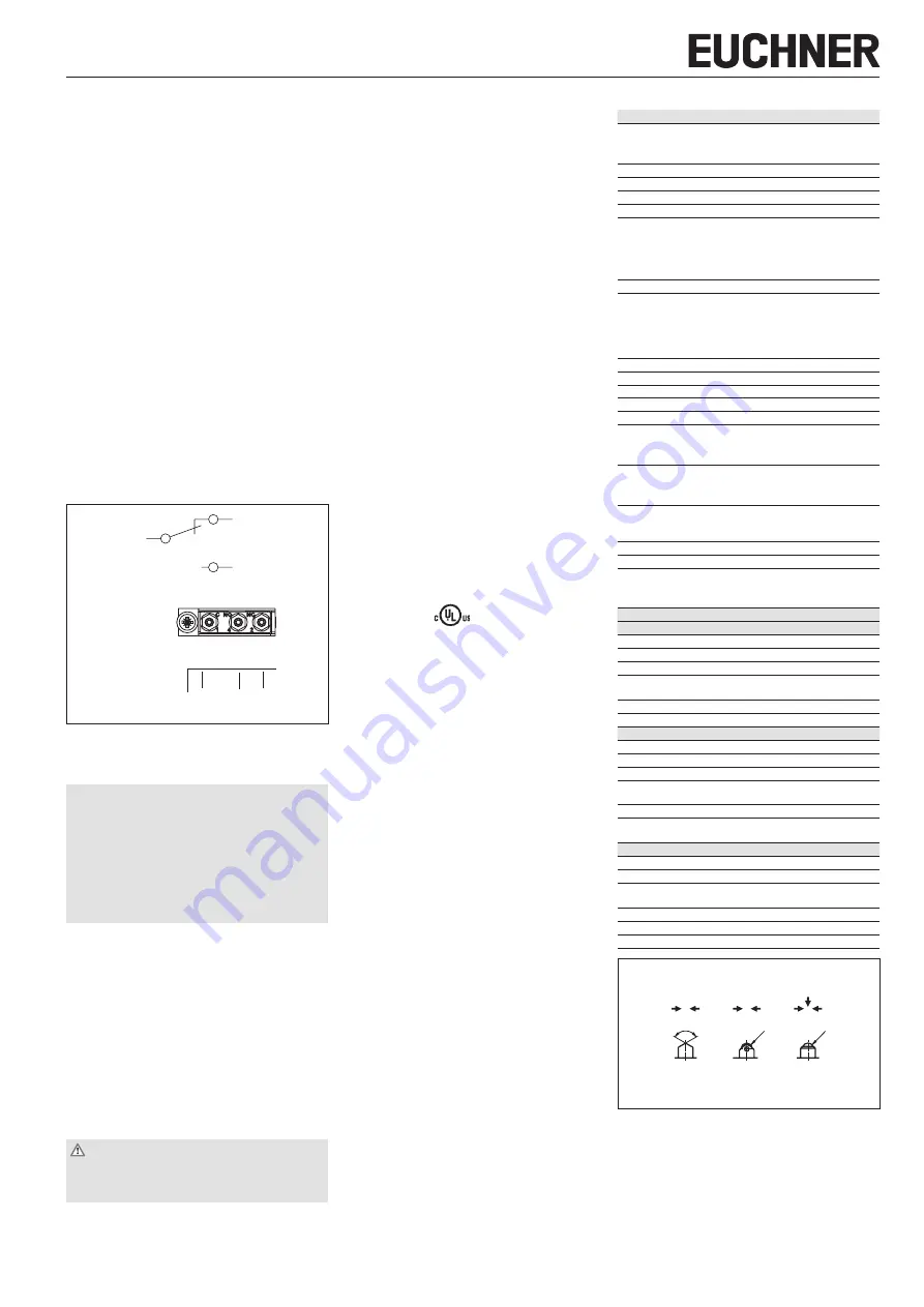
Switching elements / terminal
assignment
ES 552
ES 614
1
2
4
1
4 (NO)
2 (NC)
(C)
Top view of the switching elements
2
4
1
ES 592
Fig. 1: Switching elements and terminal assignment
Mounting
NOTICE
Device damage due to improper mounting and
unsuitable ambient conditions
f
Precision multiple limit switches must not be
used as an end stop.
f
The specified IP degree of protection is applica‑
ble only if the housing screws, cable entries and
plug connectors are properly tightened. Observe
the tightening torques.
Fit precision multiple limit switches so that
f
connecting cables and plug connectors are not
damaged by moving parts of the machine
f
sealing is ensured on cable entry through the base.
Protection against environmental
effects
Safety venting valves are used to equalize the
pressure to protect against the pumping action of
the plunger. They must not be sealed with paint.
f
Mask plunger, plunger guide, safety venting valves
and rating plate during painting work!
Electrical connection
WARNING
f
Strip the insulation from the ends of the individual
wires over a length of 6
±1
mm to ensure a safe
contact.
f
Open switch cover
f
Conductor cross‑section 0.14 … 1.0 mm²
f
For terminal assignment, see Fig. 1
f
Fit suitable cable gland with captive O‑ring
f
Seal cable carefully. Sealing ring must be matched
to the cable diameter
f
Tighten screws for connections to the switching
element to 0.2 Nm
f
Close switch cover and tighten cover screws to
0.5 Nm.
Function test
Mechanical function test
f
Actuate plunger and check the switching functions.
Electrical function test
f
Check correct function sequence.
Service and inspection
No servicing is required.
Regular inspection
of
the following is necessary to ensure trouble‑free
long‑term operation:
f
correct switching function
f
secure mounting of components
f
precise adjustment of trip dogs in relation to
multiple limit switch
f
dirt and wear
f
sealing of cable entry
f
loose cable connections.
Exclusion of liability under the
following circumstances:
f
Incorrect use
f
Non‑compliance with safety regulations
f
Installation and electrical connection not per‑
formed by authorized personnel
f
Failure to perform functional checks.
Notes about
The following information applies to devices
with plug connector:
This device is intended to be used and applied with
a Class 2 power source in accordance with UL1310.
Connecting cables for safety switches installed at
the place of use must be separated from all moving
and permanently installed cables and un‑insulated
active elements of other parts of the system that
operate at a voltage of over 150 V. A constant
clearance of 50.8 mm must be maintained. This
does not apply if the moving cables are equipped
with suitable insulation materials that possess an
identical or higher dielectric strength compared to
the other relevant parts of the system.
EU declaration of conformity
The declaration of conformity is part of the operating
instructions, and it is included as a separate sheet
with the device.
The original EU declaration of conformity can also
be found at: www.euchner.com
Service
If servicing is required, please contact:
EUCHNER GmbH + Co. KG
Kohlhammerstraße 16
70771 Leinfelden‑Echterdingen
Service telephone
:
+49 711 7597‑500
:
Internet
:
www.euchner.com
Technical data
Parameter
Value
Housing material
Series
GL, GS
Sand‑cast aluminum, anodized
SB, SN
Die‑cast aluminum, anodized
Plunger material
Stainless steel
Degree of protection
IP67
Mech. operating cycles
30 x 10
6
Actuation frequency
≤
200 min
‑1
Ambient temperature with switching element
ES 552, ES 614
‑5 … +80 °C
ES 592
‑5 … +125 °C
(manufacturer’s data max.
+140 °C)
Installation orientation
Any
Approach speed, max.
Plunger
Chisel D
20 m/min
Roller R (slide
bearing)
50 m/min
Ball K
8 m/min
Approach speed, min.
0.01 m/min
Actuating force
≥
15 N
Switching element
1 changeover contact
Switching principle
Snap‑action switching contact
Switching hysteresis max.
0.1 mm
Contact material
ES 552, ES 592
Silver
ES 614
Gold cross cut contacts
Connection
ES 552, ES 614
Screw terminal
ES 592
Soldered connection
Tightening torque of screw
terminal (hexagon socket,
A/F 1.3 mm)
0.2 Nm
Conductor cross‑section
0.14 … 1.0 mm
2
Rated impulse withstand voltage U
imp
= 2.5 kV
Rated insulation voltage
with cable entry
U
i
= 250 V
with plug connector
U
i
= 50 V
Rated data for the switching elements
ES 552
Convent. thermal current I
th
6 A
Utilization category AC‑15
230 V / 2 A
Utilization category DC‑13
24 V / 2 A
Switching current, min.,
at switching voltage
10 mA
DC 24 V
Short circuit protection
6 A gG
Mechanical life
Up to 10 x 10
6
operating cycles
ES 592
Convent. thermal current I
th
3 A
Utilization category AC‑15
230 V / 3 A
Utilization category DC‑13
24 V / 1 A
Switching current, min.,
at switching voltage
10 mA
DC 24 V
Short circuit protection
3 A gG
Mechanical life
5 x 10
5
operating cycles
(manufacturer’s data 5 x 10
6
)
ES 614
Convent. thermal current I
th
2 A
Utilization category DC‑13
30 V / 1 A
Switching current, min.,
at switching voltage
1 mA
DC 5 V
Short circuit protection
2 A gG
Mechanical life
Up to 10 x 10
6
operating cycles
Ideal application
1 mA; 5 V … 0.3 A; 30 V
120
-5°
R2,5
R2
R
D
K
Preferred approach directions
Fig. 2: Plungers and approach directions