EUCHNER 098582 Operating Instructions Manual Download Page 29

29

2098039-20-02/20 (Translation of the original operating instructions)

Operating Instructions

Non-Contact Safety Switch CES-AR-C01-…

EN

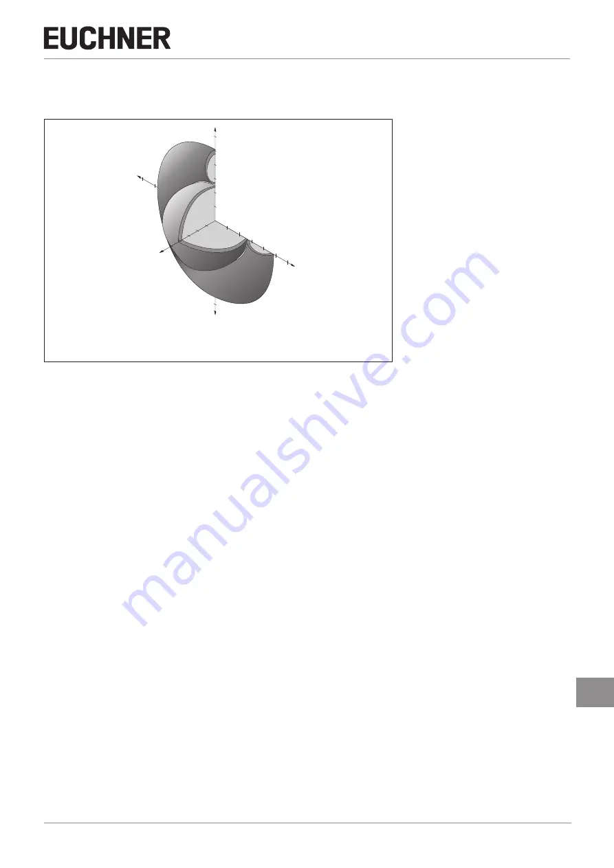
12.3.3. Typical actuating range

(only in combination with actuator CES-A-BDA-18 on surface mounting)

Y

30

25

20

15

10

5

-30

-30

-25

30

Z

15

20

25

10

5

X

25

20

15

10 5

For a side approach direction for the actuator and read head, a minimum 

distance of s = 8 mm must be maintained so that the actuating range of the 

side lobes is not entered.

Figure 7: 

Typical actuating range

Summary of Contents for 098582

Page 1: ...EN Operating Instructions Non Contact Safety Switch CES AR C01 Unicode Multicode Fixcode ...

Page 2: ... faults 11 9 3 Fuse protection for power supply 11 9 4 Requirements for connecting cables 12 9 5 Maximum cable lengths 12 9 5 1 Determining cable lengths using the example table 13 9 6 Connector assignment of safety switch CES AR 14 9 7 Connector assignment of Y distributor 15 9 8 Connection of a single AR device 16 9 9 Connection of several devices in a switch chain 17 9 10 Information on operati...

Page 3: ...2 2 2 Operating distances 26 12 2 3 Typical actuating range 27 12 3 Technical data of actuator CES A BDA 18 28 12 3 1 Dimension drawing 28 12 3 2 Operating distances 28 12 3 3 Typical actuating range 29 12 4 Technical data of actuator CES A BPA 30 12 4 1 Dimension drawing 30 12 4 2 Operating distances 30 12 4 3 Typical actuating range 31 12 5 Technical data of actuator CES A BRN 32 12 5 1 Dimensio...

Page 4: ...t is available for download at www euchner com DANGER WARNING CAUTION Safety precautions Danger of death or severe injuries Warning about possible injuries Caution slight injuries possible NOTICE Important Notice about possible device damage Important information Tip Useful information 1 4 Supplementary documents The overall documentation for this device consists of the following documents Documen...

Page 5: ...ct use includes observing the relevant requirements for installation and operation particularly based on the following standards Ì EN ISO 13849 1 Ì EN ISO 14119 Ì EN 60204 1 The safety switch is only allowed to be operated in conjunction with the intended EUCHNER CES actuators and the related connection components from EUCHNER On the use of different actuators or other connection components EUCHNE...

Page 6: ...he safe function of the safeguard should be checked at suitable intervals as part of the maintenance schedule WARNING Danger to life due to improper installation or due to bypassing tampering Safety components fulfill a personnel protection function Ì Safety components must not be bypassed turned away removed or otherwise rendered ineffec tive On this topic pay attention in particular to the measu...

Page 7: ...biguous assignment ensures a particularly high level of protection against tampering When the guard is closed the actuator is moved towards the safety switch When the operating distance is reached power is supplied to the actuator by the switch and data are transferred If a permissible code is detected the safety outputs are switched on The safety outputs are turned off when the guard is opened In...

Page 8: ...ace The plug connector can be realigned in 45 steps to change the direction of the cable outlet if elbow connectors are used 1 Remove the top part of the mounting base and push the bottom part of the mounting base off the read head 2 Unscrew the screws on the fastening bracket 3 Undo the read head from the fastening bracket and tilt the read head forward by 90 The active face is now pointing downw...

Page 9: ...stances change as a function of the installation depth and the guard material Operating distance Actuator Operating distance Actuator Flush mounting Surface mounting Note the following points Ì Actuator and safety switch must be easily accessible for inspection and replacement Ì Actuator and safety switch must be fitted so that the front faces are at the minimum operating distance 0 8 x Sao or clo...

Page 10: ...ocesses Ì The inputs on a connected evaluation unit must be positive switching as the two outputs on the safety switch deliver a level of 24 V in the switched on state Ì All the electrical connections must either be isolated from the mains supply by a safety transformer according to IEC 61558 2 6 with limited output voltage in the event of a fault or by other equivalent isolation measures PELV Ì A...

Page 11: ...he UL category code CYJV2 or CYJV must be used 1 Note on the scope of the UL approval the devices have been tested as per the requirements of UL508 and CSA C22 2 no 14 protection against electric shock and fire 9 2 Safety in case of faults Ì The operating voltage UB is reverse polarity protected Ì The safety outputs are short circuit proof Ì A short circuit between the safety outputs is detected b...

Page 12: ...with respect to the connecting cables Parameter Value Unit Conductor cross section min 0 34 mm R max 60 W km C max 120 nF km L max 0 65 mH km Recommended cable type LIYY 8x or 5 x 0 34 mm 9 5 Maximum cable lengths Switch chains are permitted up to a maximum overall cable length of 200 m taking into account the voltage drop as a result of the cable resistance see table below with example data and c...

Page 13: ...wnstream that consumes 75 mA at each of the two safety inputs This operates over the whole temperature range with a voltage of 19 2 V corresponds to 24 V 20 All the relevant values can now be determined using the example table 1 Select the corresponding section in the column n max number of switches In this case 6 switches 2 In column IOUT possible output current per channel OA OB find a current g...

Page 14: ...B 0V IA IB OA OB OUT RST View of connection side on the safety switch Coding lug Figure 2 Connector assignment of safety switch CES AR Pin Designation Description Conductor coloring 1 IB Enable input for channel 2 WH 2 UB Power supply DC 24 V BN 3 OA Safety output channel 1 GN 4 OB Safety output channel 2 YE 5 OUT Monitoring output GY 6 IA Enable input for channel 1 PK 7 0V Ground DC 0 V BU 8 RST ...

Page 15: ...B X3 2 IA X3 3 0 V X3 4 IB X3 5 RST 12 12 097627 45 15 1 4 8 5 6 3 1 2 7 35 1 20 5 1 2 4 5 3 3 4 2 1 5 M x1 Ø 14 6 M x1 Y distributor 097627 Socket Connector assignment of safety switch CES AR 8 pin plug and Y distributor 8 pin socket Pin Function X1 1 IB X1 2 UB X1 3 OA X1 4 OB X1 5 OUT X1 6 IA X1 7 0 V X1 8 RST M12x1 44 45 41 15 M12x1 15 15 M12x1 33 A B 4 8 5 6 3 1 2 7 1 2 4 5 3 3 4 2 1 5 Length...

Page 16: ...to incorrect connection Ì To ensure safety both safety outputs OA and OB must always be evaluated Important The example shows only an excerpt that is relevant for the connection of the CES system The example illustrated here does not show complete system planning The user is responsible for safe integration into the overall system Detailed application examples can be found at www euchner com Simpl...

Page 17: ...stem cannot however detect which safety door is open or on which switch a fault has occurred with this connection technology A special AR eval uation unit is required for this purpose see chapter 9 10 Information on operation on an AR evaluation unit on page 19 The series connection can also be realized via additional terminals in a control cabinet The safety outputs are permanently assigned to th...

Page 18: ...V IB RST 2 4 1 UB IA IB Safety Outputs Read Head Read Head Safety Outputs Safety Inputs Safety Inputs Y distributor Y distributor Y distributor Terminating plug Eval Unit Read Head Safety Outputs Safety Inputs 5 OUT 4 OB 2 UB 8 RST 6 IA 1 IB 7 0V 5 OUT 3 OA 4 OB 2 UB 8 RST 6 IA 1 IB 7 0V 0V 3 OA 4 OB S1 12 11 14 2 UB 8 RST 6 IA 1 IB 7 0V 5 OUT 3 OA 24V CES CES CES Figure 4 Connection example for s...

Page 19: ...this output must provide sufficient electrical current Ì Always connect inputs IA and IB directly to a power supply unit or to outputs OA and OB of another EUCHNER AR device series connection Pulsed signals must not be present at inputs IA and IB Ì The safety outputs OA and OB can be connected to the safe inputs of a control system Prerequisite The input must be suitable for pulsed safety signals ...

Page 20: ...put Y distributor Y distributor Y distributor Terminating plug ET200 4 8 F DI 4 F DO X1 X1 Digital Output PWR Supply of the control DI4 DI0 DO M DO P DO 2 DC24V 3 M 2 UB 8 RST 6 IA 1 IB X2 3 LED1 X2 4 UCM X2 5 J 7 0V 5 OUT 3 OA 4 OB X2 1 0V UCM 2 UB 8 RST 6 IA 1 IB 7 0V 5 OUT 3 OA 4 OB 2 UB 8 RST 6 IA 1 IB 7 0V 5 OUT 3 OA 4 OB 24V 0V CES CET CES Figure 5 Connection example for mixed series connect...

Page 21: ...ut The disabled code is released again in the safety switch only after a third code has been taught in Ì The safety switch can be operated only with the last actuator taught in Ì The number of teach in operations is unlimited Ì If the switch detects the actuator that was most recently taught in when in the teach in standby state this state is ended immediately and the switch changes to normal oper...

Page 22: ...e for the teach in operation and teaching in actuator on page 21 3 Close all guards in the chain 4 Actuate the reset for at least 3 s 24 V on RST On the safety switch that is positioned at a new actuator the green LED flashes at approx 1 Hz and the actuator is taught in This takes approx 1 min Do not switch off during this time and do not actuate reset The teach in operation has ended when all LED...

Page 23: ...tor only short time after power up closed off 1 Hz Teach in operation X off Positive acknowledgment after completion of teach in operation only unicode Fault display X off 2 x Input fault e g missing test pulses illogical switch state from preceding device in the switch chain closed off 3 x Defective actuator e g fault in code or code not readable X off 4 x Output fault e g short circuits loss of ...

Page 24: ...5 UB V DC HIGH U OB LOW U OA U OB 0 1 Switching current per safety output 1 400 mA Utilization category acc to EN IEC 60947 5 2 DC 13 24 V 400 mA Caution Outputs must be protected by a free wheeling diode in the case of inductive loads Off state current Ir 0 25 mA Monitoring output OUT 1 p switching short circuit proof Output voltage 0 8 x UB UB V DC Max load 200 mA Rated insulation voltage Ui 300...

Page 25: ...he latest after the risk time If several devices are operated in a series connection the risk time of the overall device chain will increase with each device added Use the following calculation formula tr tr e n x tl tr Total risk time tr e Risk time single device see technical data tl Risk time delay per device n Number of additional devices total number 1 Discrepancy time The safety outputs OA a...

Page 26: ...n IP65 IP67 IP69 IP69K Installation orientation Active face opposite read head Power supply Inductive via read head 12 2 1 Dimension drawing CES A B 071840 25 ø8 ø4 5 42 32 0 1 12 4 6 Active face Active face NOTICE 2 safety screws M4x14 included 12 2 2 Operating distances Actuating range for center offset m 0 1 Parameter Value Unit min typ max Operating distance 18 mm Assured operating distance sa...

Page 27: ...3 Typical actuating range only in combination with actuator CES A BBA X 2 5 1 5 2 0 1 0 5 20 25 30 5 10 15 30 30 30 25 20 15 10 5 Y Z For a side approach direction for the actuator and safety switch a minimum distance of s 4 mm must be maintained so that the actuating range of the side lobes is not entered Figure 6 Typical actuating range ...

Page 28: ... 18 x 9 mm Weight 0 003 kg Ambient temperature 25 70 C Degree of protection IP65 IP67 Installation orientation Active face opposite read head Power supply Inductive via read head 12 3 1 Dimension drawing 18 9 4 4 7 Active face Active face NOTICE 1 safety screw M4x14 included 12 3 2 Operating distances Actuating range for center offset m 0 1 Parameter Value Unit min typ max Operating distance 19 mm...

Page 29: ...ctuating range only in combination with actuator CES A BDA 18 on surface mounting Y 30 25 20 15 10 5 30 30 25 30 Z 15 20 25 10 5 X 2 5 2 0 1 5 1 0 5 For a side approach direction for the actuator and read head a minimum distance of s 8 mm must be maintained so that the actuating range of the side lobes is not entered Figure 7 Typical actuating range ...

Page 30: ...P67 IP69 IP69K Installation orientation Active face opposite read head Power supply Inductive via read head 12 4 1 Dimension drawing 30 0 1 40 0 25 0 CES A BPA 098775 IP67 CD 10 4 Ø 5 2 Active face Active face NOTICE 2 safety screws M5x10 included 12 4 2 Operating distances Actuating range for center offset m 0 1 Parameter Value Unit min typ max Operating distance 22 mm Assured operating distance ...

Page 31: ...ange only in combination with actuator CES A BPA on surface mounting 45 40 35 30 25 20 15 10 45 5 Z Y X 5 10 15 20 25 30 35 40 45 45 40 45 35 30 25 20 15 10 5 For a side approach direction for the actuator and read head a minimum distance of s 6 mm must be maintained so that the actuating range of the side lobes is not entered Figure 8 Typical actuating range ...

Page 32: ...ation Active face opposite read head Power supply Inductive via read head 12 5 1 Dimension drawing 40 80 10 3 5 5 17 11 17 11 15 8 5 Active face Active face NOTICE 2 safety screws M5x16 included 12 5 2 Operating distances Actuating range for center offset m 0 1 Parameter Value Unit min typ max Operating distance 27 mm Assured operating distance sao 20 Switching hysteresis 3 Assured release distanc...

Page 33: ... actuator CES A BRN on surface mounting on metal 5 2 0 2 5 3 0 3 5 Z X 5 15 20 50 45 40 35 30 25 50 Y 5 10 15 20 25 30 35 40 45 50 55 60 65 10 5 15 25 30 40 45 50 55 60 65 1 5 1 0 10 20 35 For a side approach direction for the actuator and read head a minimum distance of s 6 mm must be maintained so that the actuating range of the side lobes is not entered Figure 9 Typical actuating range ...

Page 34: ...es or spare parts that can be ordered from EUCHNER may be replaced Regular inspection of the following is necessary to ensure trouble free long term operation Ì Check the switching function see chapter 10 3 Functional check on page 22 Ì Check the secure mounting of the devices and the connections Ì Check for soiling No servicing is required Repairs to the device are only allowed to be made by the ...

Page 35: ...35 2098039 20 02 20 Translation of the original operating instructions Operating Instructions Non Contact Safety Switch CES AR C01 EN 16 Declaration of conformity ...

Page 36: ...Operating Instructions Non Contact Safety Switch CES AR C01 36 Translation of the original operating instructions 2098039 20 02 20 ...

Page 37: ...37 2098039 20 02 20 Translation of the original operating instructions Operating Instructions Non Contact Safety Switch CES AR C01 EN ...

Page 38: ...Operating Instructions Non Contact Safety Switch CES AR C01 38 Translation of the original operating instructions 2098039 20 02 20 ...

Page 39: ...39 2098039 20 02 20 Translation of the original operating instructions Operating Instructions Non Contact Safety Switch CES AR C01 EN ...

Page 40: ...uchner com Edition 2098039 20 02 20 Title Operating Instructions Non Contact Safety Switch CES AR C01 Translation of the original operating instructions Copyright EUCHNER GmbH Co KG 02 2020 Subject to technical modifications no responsibility is accept ed for the accuracy of this information ...

Reviews: