※
The contents of this manual are updated without prior notice. If the function of the product you are using is inconsistent with the instructions, the function of the product shall prevail.Please contact us if you have any questions.
1.The product shall be tested and installed by qualified personnel.
2.This product cannot be waterproof, so it needs to avoid the sun and rain. If it is installed
outdoors, please use the waterproof water tank.
3.Before power-on debugging, ensure all wiring is correct to avoid lamp damage caused
by wrong wiring. Power supply should be within the voltage range, exceeding the voltage
range may burn out the controller.
4.Before electrification, please ensure that all wiring positive and negative poles
correspond correctly. Please check that there is no short circuit between the input and
output wires.
5.Good heat dissipation will prolong the service life of the controller. Please install the
product in a well-ventilated environment.
6.The size of the wires used must be sufficient to load the connected lamps and ensure
the wiring is firm.
7.In case of failure, please do not repair without permission. If you have any questions,
please contact the supplier.
1.Purchase ochase LED controller for technical support and warranty.
·Free warranty; Ochase will provide repair or replacement service if any product quality
problem occurs within 5 years from the date of purchase
·Paid insurance: appropriate maintenance material costs will be charged for products
beyond the free warranty period.
2.The following circumstances are not covered by the free warranty or replacement service.
·Over high pressure, over load, improper operation and other man-made damages
·Product appearance is seriously damaged or deformed
·Product warranty label and product unique bar code are damaged
·Products have been updated
3.Repair or replacement is ochs 'only remedy to the customer and ochs shall not be liable for
any incidental damages.
4.Only ochase has the right to modify or adjust this warranty, and shall issue a written
confirmation.
Caution
Installation guide
Warranty Agreement
Touch Panel
2/2
User’s manual: 2019-12
www.euchips.com
RF Connection Description
1. Code matching: select the receiver that needs code matching, cut off the power supply
for 10 seconds and then switch on the power supply again. Click "group open 1" for 3 times
within 5 seconds after switching on the power supply.
2. Code clearance: select the receiver that needs to be cleared, cut off the power supply
for 10 seconds and then switch on the power supply again. Click "group open 1" button 6
times within 5 seconds of switching on the power supply.
Brightness control key:
Brightness Adjustment Key:
Press + to increase the brightness of the selected area, and press - to decrease the
brightness of the selected area To adjust.
Touch Ring
:
After the user selects the corresponding area, he can adjust the luminaire brightness of
the selected area by swiping the color ring with his finger (it is not available in scene
mode).
Select a single area or all areas and press the 25% brightness key to change the lights in
that area to 25% brightness. Press the 50% brightness key to change the light in the area
to 50% brightness. Press the 75% brightness key to change the light in this area to 75%
brightness. Press the 100 brightness key and the light in the area becomes 100
brightness.
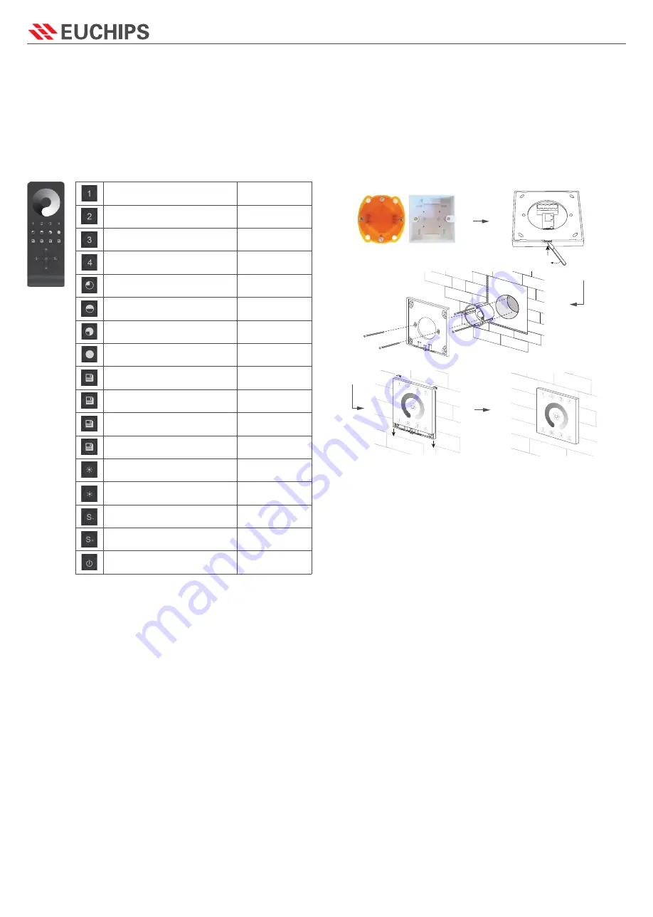
Whether The Panel Corresponds To The Remote Control Is Shown In The Right Picture:
Group 1
Group 2
Group 3
Group 4
Scene 1
Scene 2
Scene 3
Scene 4
ALL key, achieve four groups at the
same time control
B +, brig
B +, brightness -
Might key to perform a low brightness
scene
Brightness plus, divided into ten levels
Brightness reduction, divided into
ten levels
Brightness ALL OFF 0%
Brightness ALL ON 100%
Turn ON/OFF
Non-corresponding
Panel
Non-corresponding
Panel
Non-corresponding
Panel
Non-corresponding
Panelsponding Panel
Non-corresponding
Panel
Non-corresponding
Panel
Non-corresponding
Panel
Non-corresponding
Panel
Corresponding Panel
Corresponding Panel
Corresponding Panel
Corresponding Panel
Corresponding Panel
Corresponding Panel
Corresponding Panel
Corresponding Panel
Corresponding Panel
1.Mount an electrical box inside the wall
2.To separate the glass panel and the back cover of the controller with a screwdriver along
the gap of the back cover.
3.To put the back cover on the electrical box and fix it with the screw.
5.To buckle the glass panel to the back cover.
4.Connect the wires
DMX: Connect the DMX cable to the DMX interface
Power: Make sure to not invert the + and the ground


