background image

Page 12 

OTHER CONNECTIONS 

OTHER CONNECTIONS 

C

ONNECTING THE TELEPHONE LINE


PSTN line or universal GSM gateway 

Connect the ground terminal (indicated by

), to a ground socket in 

order to increase the telephone line protection. 

Connect the telephone line to terminal LTI.

C

ONNECTING THE LOCAL TELEPHONE


Connect the local telephone (for programming and managing the
device) directly to the RJ11 connector (M in the picture at page 2) or to
TEL and – terminals (irrespective of the polarity).

C

ONNECTING THE FILTER INPUT


Connect the filter contact as per one of the modes shown in the table:

C TERMINAL 

CONNECTED TO: 

FILTER CONTACT 

TERMINAL BLOCKS 

+12

IN1 / 


IN1 / +12 

external reference 

IN1 / external reference 

Note: if a 2W speak

er

 unit  is installed in the cabin, it is possible to 

use the terminal block’s filter input of the speak

er

 unit (AUX 

and – terminal blocks). 

C

ONNECTING THE RELAY


Connect the output RL1 (normally open contact) to the external device.

Summary of Contents for Esse-ti HELPY 2W-V

Page 1: ...05 06 2018 AUTODIALER SYSTEM FOR LIFTS MANUAL HELPY 2W V...

Page 2: ...Card slot C Device status LED D Serial port for PC connection E Reset pushbutton F Terminal blocks G Built in loudspeaker H Given alarm indicator light I Received alarm indicator light L Built in mic...

Page 3: ...ingle microphone Input for connecting microphone of passive speaker unit or single microphone Negative TEL Local telephone RL1 Relay 4 RL1 Relay 4 LTI LTI BUS BUS TX RX Ground terminal for telephone l...

Page 4: ...it The passive speaker unit can be installed at max 6 m distance from Helpy 2W V or from 2W speaker unit by using a shielded cable Each 2W speaker unit connected over the bus the built in speaker uni...

Page 5: ...2 Vdc AR AI AR AI Negative Green LED Received alarm indicator light light positive pole Red LED Given alarm indicator light light positive pole Green LED Received alarm indicator light light negative...

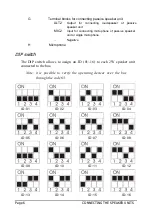
Page 6: ...onnecting microphone of passive speaker unit or single microphone Negative H Microphone DIP switch The DIP switch allows to assign an ID 01 16 to each 2W speaker unit connected to the bus Note it is p...

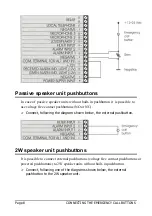
Page 7: ...L BUTTONS Car pushbutton It is possible to connect inside the elevator car voltage free contact pushbuttons or powered pushbuttons Connect following one of the diagrams shown below the car pushbutton...

Page 8: ...e contact pushbuttons NO or NC Connect following the diagram shown below the external pushbutton 2W speaker unit pushbuttons It is possible to connect external pushbuttons voltage free contact pushbut...

Page 9: ...CONNECTING THE EMERGENCY CALL BUTTONS Page 9 this solution is allowed only if the negative pole of Helpy 2W V is not connected to the negative pole of the lift...

Page 10: ...utton to indicate the beginning of the alarm procedure The RECEIVED ALARM INDICATOR LIGHT green switches on when the alarm call is answered Some Helpy 2W V models come with built in indicator lights I...

Page 11: ...ights Some 2W speaking unit models come with built in indicator lights It is also possible to connect external indicator lights Connect following one of the diagrams shown below the external indicator...

Page 12: ...directly to the RJ11 connector M in the picture at page 2 or to TEL and terminals irrespective of the polarity CONNECTING THE FILTER INPUT Connect the filter contact as per one of the modes shown in...

Page 13: ...the external contact to AL2 and terminals Note the AL2 input can be configured either as normally open or closed 2W speaker unit 2W speaker units come with an AUX input configurable as auxiliary inpu...

Page 14: ...Page 14 WIRING DIAGRAMS WIRING DIAGRAMS WIRING DIAGRAM WITH 2W SPEAKING UNITS ON CAR TOP AND IN THE PIT...

Page 15: ...WIRING DIAGRAMS Page 15 WIRING DIAGRAM WITH PASSIVE SPEAKING UNITS...

Page 16: ...Page 16 WIRING DIAGRAMS WIRING DIAGRAM WITH LANDING FLOORS...

Page 17: ...t and dial Make an external call to check the PSTN line or the universal GSM gateway is properly working dial and key in the telephone number to make a test call 2 TESTING THE ALARM PROCEDURE Press th...

Page 18: ...c reset Hang up or press to end the alarm 3nd mode automatic reset with local acknowledgement Hang up to end the call Close the reset input AL2 or IN1 to end the alarm An end of alarm call will be gen...

Page 19: ...e at page 2 Pressing shortly Allows to interrupt an alarm call By pressing shortly you get the same result as lifting the handset of the local telephone and entering Password Pressing longer 10 second...

Page 20: ...INSTALLER or OPERATOR PASSWORD factory default EXITING THE PROGRAMMING INSTALLER or OPERATOR PASSWORD factory default TELEPHONE NUMBERS INST the programming of the telephone number automatically activ...

Page 21: ...SATURDAY TIME INST hhmm from 0000 to 2359 RECORD MESSAGES INST Site information message max 25s record hang up Calm down message max 25 s LISTEN TO MESSAGES INST OPER Site information message listen...

Page 22: ...00 to 2359 Automatic test alarm automatic test disabled automatic test enabled Make a test call manually PROTOCOLS IDENTIFICATION CODE INST Esse ti identification code P100 SPEAKER UNITS VOLUME INST O...

Page 23: ...NPUT SETTINGS INST AL2 alarm input IN1 filter input AL2 auxiliary input IN1 filter input AL2 reset input IN1 filter input AL2 alarm input IN1 reset input AL2 auxiliary input IN1 reset input 2W SPEAKER...

Page 24: ...lit and no courtesy message HANDSFREE CONNECTION MODE DURING AN ALARM INST handsfree activation by Handsfree activation code automatic handsfree activation after messages immediate and automatic hands...

Page 25: ...IR IS KW MO MW MX PY UY VE YE ZM 10 HR 11 GR EE FI 12 NL AW VU 13 SI 14 HU 15 IL 16 AT 17 AU 18 CH 19 CN 20 US CA JM 21 BE 22 QA 23 SE 24 IN 25 TR DURATION OF COMMUNICATION PERIOD INST minutes from 2...

Page 26: ...behaviour as outputs AR active for external power failure door opener active as long as the emergency alarm progresses active as long as the buttons are pressed active for telephone line absence RELA...

Page 27: ...PROGRAMMING Page 27 ADVANCED PROGRAMMING LISTEN TO THE EXTERNAL POWER SUPPLY LEVEL INST expressed in mV...

Page 28: ...the messages of the Helpy 2W V set a micro SD card to use for programming customizing the messages and updating the firmware of the Helpy 2W V e stant can be downloaded at the following link http www...

Page 29: ...VATE ALL EXTERNAL CALLS TELEPHONE NUMBER DOOR OPENER RELAY Use remotely with Helpy 2W V in dormant mode Call Helpy 2W V and wait for a response After listening to the elevator identification message d...

Page 30: ...EVICE STATUS LED Normal operation no alarm Alarm Voice connection Battery disconnected or low battery max 1 hour operation in idle state 2W speaker unit connection error or bus problem Absence of tele...

Page 31: ...NOTE Page 31 NOTE...

Page 32: ...ETL UK Electromatic Tele Link Limited Tel 44 0 1621 856 230 E mail info etluk eu Web www etluk eu...

Reviews: