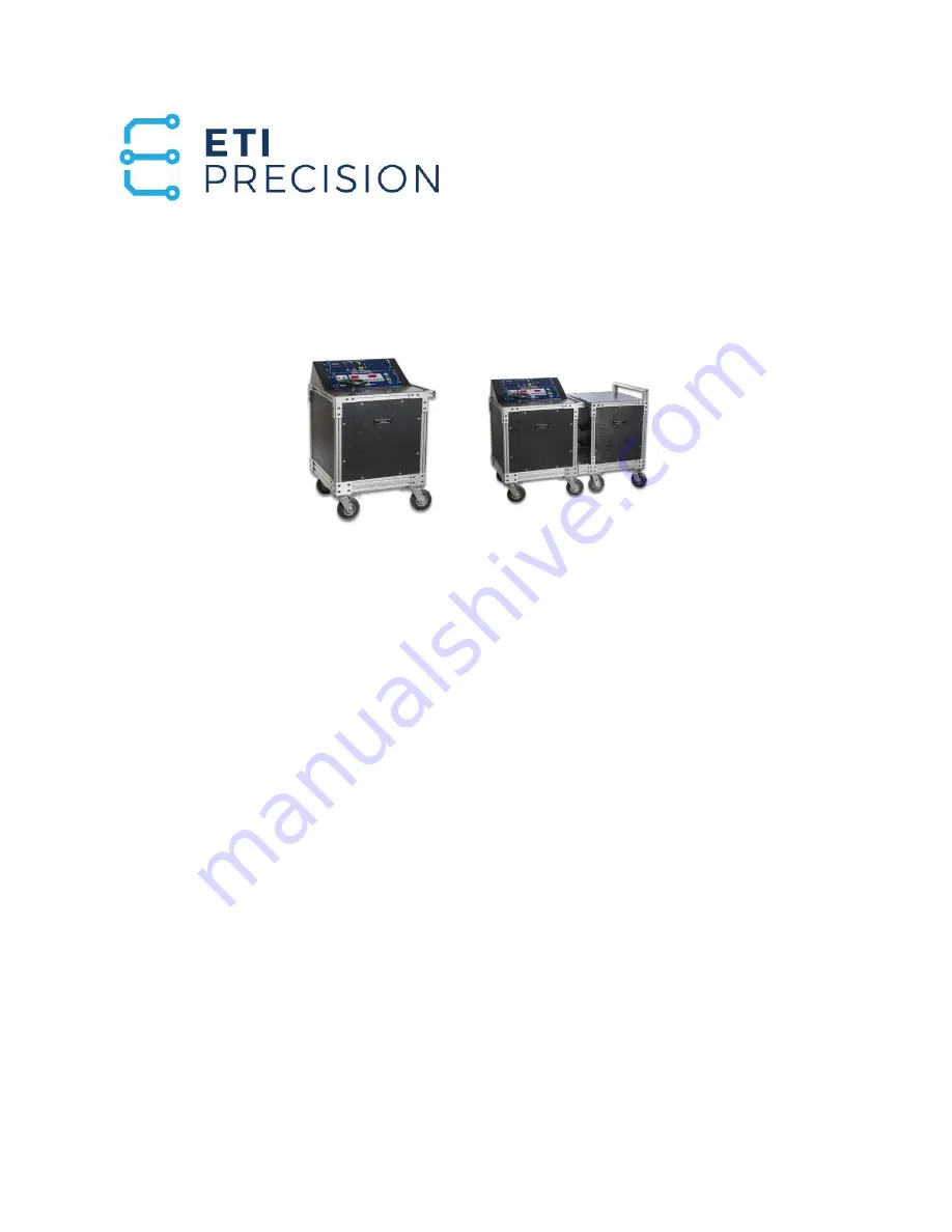
PRIMARY INJECTION CIRCUIT BREAKER
TEST SET
INSTRUCTION MANUAL
Models
PI-2500 and PI-5000
Electrical Test Instruments, LLC.
8430 Spires Way, Suite A-F
Fredrick, MD 21701
www.ETIPrecision.com
(410) 857-1880
Fax (410) 857-1387
Page 1: ... INJECTION CIRCUIT BREAKER TEST SET INSTRUCTION MANUAL Models PI 2500 and PI 5000 Electrical Test Instruments LLC 8430 Spires Way Suite A F Fredrick MD 21701 www ETIPrecision com 410 857 1880 Fax 410 857 1387 ...
Page 2: ...uitry II 1 PI 2500 Control Circuitry II 1 AUX 5000 Main Circuitry II 1 AUX 5000 Control Circuitry II 1 PI 2500 Indicator Control Panel Circuitry II 4 MAC 20 Monitor Controller Circuitry II 4 MAC 20 Software II 5 Major Parts Identification and Operation MAC 20 Control Panel II 6 MAC 20 Internal Parts II 9 Figure II 1 Front Panel II 10 Indicator Control Panel II 11 Figure II 2 Retrofit Indicator Pan...
Page 3: ... Voltage Power Breakers IV 10 Motor Overload Relays IV 14 Ratioing Current Transformers IV 16 SECTION V SERVICE INFORMATION AND DOCUMENTATION Maintenance and Calibration of PI 4000B V 1 Maintenance and Calibration of MAC 20 V 1 Parts List PI 2500 V 4 Parts List AUXI 5000 V 4 Parts List Indicator Control Panel V 5 Parts List MAC 20 V 6 Overall Schematic PI 2500 V 7 Overall Schematic AUX 5000 V 7 Ov...
Page 4: ...Electrical Test Instruments PI 2500 and PI 5000 Section II Detailed Description Copyright C 1994 2008 Electrical Test Instruments LLC All Rights Reserved SECTION I GENERAL INFORMATION ...
Page 5: ...WARNING READ THIS ENTIRE MANUAL AND THOROUGHLY FAMILIARIZE YOURSELF WITH THE UNIT OPERATION PRIOR TO CONNECTING THE UNIT TO A SOURCE OF POWER HIGH CURRENT TEST SETS ARE NORMALLY POWERED FROM HIGH CAPACITY 208 VOLT TO 575 VOLT SERVICES AND IMPROPER CONNECTION OR OPERATION COULD CAUSE DAMAGE TO THE TEST SET AND EQUIPMENT UNDER TEST AS WELL AS CREATE AN UNSAFE CONDITION FOR PERSONS OPERATING THE SET ...
Page 6: ...op for easy access to internal components The sides are clear of protruding components and a full width handle facilitates moving the unit Locking pneu matic swivel castors on one end provide ease of mobility and allow the test set to be moved on rough surfaces The indicator control panel and MAC 20 are mounted in a compact hood on the top which provides protection during transportation A flat are...
Page 7: ...trol panel If the switch is held the taps change at a rate of about two seconds per tap Tap change is not allowed when output is on Note Output taps 1 3 only for the PI 2500 Output taps 4 9 are only operational when the AUX 5000 section is con nected to the PI 2500 section The indicator control panel features two temperature indicators one for the output bus temperature and the other for the overa...
Page 8: ...ontains most of the circuitry facilitating service and maintenance The rear panel may be removed for access to input fuses control fuses and the SCR board A large bottom mounted fan provides airflow to the transformer and output bus The cabinet is designed with no pro truding components on the sides so it can be navigated through narrow door ways without problems The input jacks and voltage switch...
Page 9: ...e PI 2500 The con nectors are color coded and must be connected with black to black and red to red There is also a control cable which connects from the AUX 5000 to the PI 2500 The output of the AUX 5000 is identical to that of the PI 4000B and accom modates standard breaker stabs for continuous output of 4000 amperes It can also be configured in series mode for a continuous output of 2000 am pere...
Page 10: ...es mode with a resolution of 0 001 second or 0 5 cycle A preset function allows you to set a maximum ON time in seconds or cycles for con venient jogging of output to desired current or setting time for heat runs and long time tests A current hold feature is also built in When the desired current is displayed a simple touch of the MAINTAIN key activates the function which automatically adjusts the...
Page 11: ...15 Minutes 64 128 6000 A 3000 A 3x 10 1 5 Minutes 15 Minutes 96 192 8000 A 4000 A 4x 6 45 Seconds 15 Minutes 128 256 10000 A 5000 A 5x 4 4 Seconds 2 Minutes 160 320 14000 A 7000 A 7x 2 1 Second 2 Minutes 224 448 20000 A 10000 A 10x 1 0 2 Second 2 Minutes 320 640 Available with 480 VAC input only Max ON Times may be less at 208 or 240 VAC DIMENSIONS AND NET WEIGHT Height 41 in 1041 mm includes cast...
Page 12: ...es 15 Minutes 288 16000 A 8000 A 4x 6 45 Seconds 15 Minutes 384 20000 A 10000 A 5x 4 4 Seconds 2 Minutes 480 28000 A 14000 A 7x 2 1 Second 2 Minutes 672 40000 A 20000 A 10x 1 0 2 Second 2 Minutes 960 DIMENSIONS AND NET WEIGHT PI 5000 AUX Height 35 in 889 mm includes castors Width 30 0 in 762 mm Depth 25 0 in 635 mm Weight 585 lb 218kg DIMENSIONS AND NET WEIGHT PI 5000 Combined PI 2500 PI 5000AUX H...
Page 13: ...Electrical Test Instruments PI 2500 PI 5000 Section II Detailed Description Copyright C 1994 2008 Electrical Test Instruments LLC All Rights Reserved Page II 9 SECTION II DETAILED DESCRIPTION ...
Page 14: ...tective de vices etc 5 Current measurement circuitry consisting of sensors current meter and timer In general a primary voltage is selected by means of a combination of coarse tap and Vernier adjustment This voltage is stepped down by the output trans former to provide the desired current into the load impedance PI 2500 Main Unit Circuitry Main power is applied to the PI 2500 by means of standard ...
Page 15: ...ensor PCB and provides an interlock and in put selector error indication The voltage sensor PCB rapidly flashes the Input Select Error LED on the control panel for 5 seconds during startup and then turns off if input voltage is within bounds as determined by the input selector switch position If line voltage is incorrect the Input Select Error LED will flash and control power cannot be turned on I...
Page 16: ...egrees There are three solid state relays one of which powers the Vernier assembly and the others power the second primary on the output transformer The Vernier autotransformer may be adjusted manually by means of a hand wheel or by activating the motor drive Increasing output is clockwise for all taps When the SCR board is energized 12 VDC is applied to the control panel which is used for output ...
Page 17: ...he indicator control panel and an interlock relay shuts down the output of the test set if abnormal conditions are detected More details are in a separate manual The PI 2500 features a very efficient low impedance output transformer with enhanced reliability and cooler operation due to single piece secondary bus conductors It was designed so that it could provide three connection modes for 1000 20...
Page 18: ...ls are driven by 24 VDC pulses from the Auxiliary Relay PCB The primary of each trans former section is shorted when it is not needed otherwise it is powered through the SSR Electrical interlocks on the contactors assure that both cannot be pulled in at the same time The control connector to the PI2500 provide ACHI and ACLO power for the fan control signals for the contactors initiate signal for t...
Page 19: ...y contact If the output of the test set is ON 12 VDC will be applied to DS5 and also will be sensed by the PC board which will inhibit tap change The INV 4A and B signals provide a voltage equal to the input voltage This is rectified and filtered by the metering PC board and displayed on the panel me ter Output is inhibited during tap change or when an interlock condition exists An interlock INTLK...
Page 20: ...al Status System This indicates temperature of the output section and other conditions as determined by the POD A thermistor in the winding of the first section of the output transformer provides actual temperature but the POD also calculates a virtual temperature based on overload duty cycle limits as indicated in the specifications The ten bar graph LEDs correspond to tem peratures of approximat...
Page 21: ...ical Test Instruments LLC All Rights Reserved Page II 17 Figure II 2 Indicator Control Panel Thermal Status Bus Vernier ON Stab Voltage READY INTERLOCK ON OFF Output Main Control Coarse Tap Vernier Power Input Voltage 0 50 Electrical Test Instruments Inc Indicator Control Panel Power Input Selector Error ...
Page 22: ...yright C 1994 2008 Electrical Test Instruments LLC All Rights Reserved MEMORY AMMETER CONTROLLER MAC 21 INSTRUCTION MANUAL Firmware Version 3 06 and above Electrical Test Instruments LLC 1301 Avondale Road Suite J New Windsor MD 21776 www ETIPrecision com 410 857 1880 Fax 410 857 1387 ...
Page 23: ...00 5 000 25 000 100 000 Amperes CURRENT ACCURACY 0 5 Reading 0 5 Range 1 Digit Continuous 1 0 Reading 1 0 Range 1 Digit Pulse 0 01 sec TIMER RANGES 0 9 999 0 99 99 0 999 9 0 9999 Seconds 0 999 9 0 9999 Cycles TIMER ACCURACY 0 5 of reading 1 count DIMENSIONS AND NET WEIGHT Height 7 0 in 178 mm Width 19 0 in 483 mm Depth 2 0 in 51 mm Weight 3 7 lb 1 68 kg STANDARD ACCESSORIES Remote Initiate cable 1...
Page 24: ...MS value displayed in CONTINUOUS mode This is useful for pickup tests It may not be accurate for times less than 1 second INITIATE key This key is used to turn ON the output of the test set The LED in the key indicates that the MAC 21 is attempting to turn the output ON but other conditions such as interlocks could keep the output from actually turning on In MOMENTARY mode the key must be held to ...
Page 25: ...posts indicates that the protective device under test is in its normal non tripped mode and ready to accept current This mode may be used for testing multi pole breakers by connecting the CONTACTS binding posts to an unused pole In N C mode the timer starts as soon as current about 3 of range is detected after the INITIATE key is pressed and stops when the STOP key is pressed or a break in continu...
Page 26: ...et In MEMORY mode LED on the cur rent display will read the continuous output current until the test is complete At this time the LED will flash and the display will read the computed true RMS value of the entire current pulse for the duration indicated on the TIME display This key may be pressed at any time before during or after the test to toggle between the two modes As described above pressin...
Page 27: ...sabled in MAINTAIN mode unless a pre set value is set in CYCLES time base SERIAL port This standard serial port may be connected to a printer computer or other device to print or store time and current values of test results in ASCII format It is set for 9600 baud 8 bits 1 stop bit no parity no flow control This information is sent at the end of each test or by pressing the Stop and Reset keys Rep...
Page 28: ...provides 120 VAC control power and connects to the air core CT current sensor and initiate circuitry of the test set The wiring of this connector is essentially compatible with that of the EIL Accu Amp and is designed to facilitate removal of the MAC 21 for service or shipment Additional pins are used to provide isolated logic level control for motorized Vernier raise and lower for the current hol...
Page 29: ...le it is being transported and subject to shock and vibration The standard rack mount hardware and twist lock connector make it simple to remove the MAC 21 and carry it separately Field calibration of the MAC 21 may be performed as follows 1 Obtain a current measuring calibration standard capable of reading TRUE RMS current up to at least 1000 Amperes to an accuracy of at least 0 25 This may consi...
Page 30: ... timer begins to run This is the Current Latch Threshold which should be about 10 of range 11 Set the current at 50 of full scale 500 A and stop the current 12 Set the MAC 21 to MEMORY mode and press the RESET Switch 13 Initiate a fast momentary pulse of no more than 6 cycles 0 1 Sec duration The meter should read the same value within 1 of reading 1 of range that was set in step 11 above 14 Check...
Page 31: ...Number 1 1 MAC 21 Contact LED Harness S B369 2 1 MAC 21 Rear Panel Harness S B368 3 1 MAC 21 Metal Cage M D464 4 1 MAC 21 Main PCB M C492 5 1 MAC 21 Membrane Switch Panel M D462 6 6 LOCKWASHER INT TOOTH 4 M A116 7 6 SCREW PH 4 40x1 4 M A118 8 2 HANDLES BRASS NICKEL PLT 4 M C103 9 4 SCREW RH 10 32x1 2 M A158 10 4 FLATWASHER 10 M A159 11 4 LOCKWASHER 10 M A160 12 4 SCREW PH 10 32X3 4 M A191 13 4 NYL...
Page 32: ...Electrical Test Instruments MAC 21 Retrofit Package Section III MAC 21 Copyright C 1994 2003 Electrical Test Instruments LLC All Rights Reserved Connections MAC 21 ...
Page 33: ...Electrical Test Instruments MAC 20 Retrofit Package Section III MAC 20 Copyright C 1994 2008 Electrical Test Instruments LLC All Rights Reserved ...
Page 34: ...Electrical Test Instruments PI 2500 and PI 5000 Section IV Operating Instructions Copyright C 1994 2004 Electrical Test Instruments LLC All Rights Reserved SECTION IV OPERATING INSTRUCTIONS ...
Page 35: ...cables h Input ground lead i Auxiliary ground lead j Contact lead set If applicable k Remote initiate cable optional 2 For 1000 amp output mode a Attach series bars from output terminals 2 to 3 4 to 5 and 6 to 7 b Make sure they fit snugly between the output bus bars and tighten the bolts c Attach cables as needed between output terminals 1 and 8 d Make sure selector switch is set to 1000 3 For 20...
Page 36: ...in good condition a PI 2500 Main Unit b AUX 5000 Auxiliary Unit c Allen wrench hex to match socket head bolts d Pneumatic or electric power ratchet e Stab set or cables to match breaker to be tested f Series bar optional g Input power plugs and cables h Input ground lead i Auxiliary ground lead j Contact lead set If applicable k Remote initiate cable optional 2 Remove any bus work or cables from t...
Page 37: ...Test log and or report forms See examples at end of section d Basic hand tools wrench screwdriver etc e Safety equipment safety glasses gloves etc f Reliable and sufficient power source g Clean spacious and well lit work area 2 The voltage selector must be set to match input voltage 3 Calculate KVA requirements for the source per manufacturer s manual 4 Locate a suitable earth ground and connect i...
Page 38: ...test to appropriate output tap using stabs or ca bles and series bar as required 14 Make sure that breaker is CLOSED 15 Follow Step by Step procedures below as required for testing 16 When tests are completed press INTERLOCK switch to turn Main Power OFF 17 Press Control Power Off switch to turn Control Power OFF 18 Turn off supply power if possible and disconnect input power cables 19 Remove grou...
Page 39: ...ile the test set is powered up 4 Always choose an ammeter range that allows the test current to be read in the area from 20 to 80 of the maximum This provides greatest accuracy of readings least chance of overrange and optimum current latch opera tion 5 To obtain maximum output current from the test set especially when us ing output cables it is important to minimize both input and output im pedan...
Page 40: ...the INITIATE button while adjusting the OUTPUT CONTROL higher until the desired test current is read on the ammeter If insufficient current is obtained at maximum position of the Vernier set the OUTPUT TAP control to the next higher tap return the Vernier to zero and continue 10 Press RESET button 11 Set TIMEBASE to SECONDS 12 Select MAINTAIN mode 13 Press and release INITIATE key OUTPUT ON light ...
Page 41: ...ay be set higher or lower depending on trip characteristics of breaker 7 Press PRESET again to return to normal mode 8 Select MEMORY mode 9 Repeatedly jog the INITIATE button while adjusting the OUTPUT CONTROL higher until the circuit breaker trips instantaneously This is the approximate pickup point If insufficient current is obtained at maximum position of the Vernier set the OUTPUT TAP control ...
Page 42: ...above 2 Adjust controls to obtain current above pickup at approximate desired multiple of rating 3 Close breaker under test 4 Press the INITIATE button Breaker should trip instantaneously 5 Read and record timer and ammeter readings as instantaneous trip time and current 6 Shut down test set disconnect breaker and prepare for subsequent test ing or relocation according to steps 18 through 22 in pr...
Page 43: ...normal mode 9 Select MEMORY mode 10 Repeatedly jog the INITIATE button while adjusting the OUTPUT CONTROL higher until the desired test current is read on the ammeter If insufficient current is obtained at maximum position of the Vernier set the OUTPUT TAP control to the next higher tap return the Vernier to zero and continue 11 Press RESET button 12 Set TIMEBASE to SECONDS 13 Select MAINTAIN mode...
Page 44: ...esired test cur rent 5 Set TIMEBASE to CYCLES 6 Press PRESET key Adjust preset time to 5 0 cycles This value may be set higher or lower depending on trip characteristics of breaker 7 Press PRESET again to return to normal mode 8 Select MEMORY mode 9 Repeatedly jog the INITIATE button while adjusting the OUTPUT CONTROL higher until the circuit breaker trips instantaneously This is the approximate p...
Page 45: ... current above pickup at approximate desired multiple of rating 3 Close breaker under test 4 Press the INITIATE button Breaker should trip instantaneously 5 Read and record timer and ammeter readings as instantaneous trip time and current 6 Repeat the above test for the other poles of the circuit breaker 7 Shut down test set disconnect breaker and prepare for subsequent test ing or relocation acco...
Page 46: ...de timing test on L T D timing test on S T D and instantaneous pick up It is rec ommended that the magnitude of test current for the L T D timing test be 3 times coil rating or transformer tap For timing test on S T D the test current should be about 1 5 times the S T D setting In both cases tripping time should be within the manufacturer s published time range Pick up of the instantane ous unit s...
Page 47: ...d on the ammeter If insufficient current is obtained at maximum position of the Vernier set the OUTPUT TAP control to the next higher tap return the Vernier to zero and continue 11 Press RESET button 12 Set TIMEBASE to SECONDS 13 Select MAINTAIN mode 14 If desired N C mode may be used connect contacts leads to an unused pole of the breaker 15 Press and release INITIATE key CLOSE or OUTPUT ON light...
Page 48: ...ile adjusting the OUTPUT CONTROL higher until the desired test current is read on the ammeter If insufficient current is obtained at maximum position of the Vernier set the OUTPUT TAP control to the next higher tap return the Vernier to zero and continue 3 Press RESET button 4 Set TIMEBASE to SECONDS 5 Select MAINTAIN mode 6 If desired N C mode may be used connect contacts leads to an unused pole ...
Page 49: ...IMEBASE to CYCLES 6 Press PRESET key Adjust preset time to 5 0 cycles This value may be set higher or lower depending on trip characteristics of breaker 7 Press PRESET again to return to normal mode 8 Select MEMORY mode 9 Repeatedly jog the INITIATE button while adjusting the OUTPUT CONTROL higher until circuit breaker trips instantaneously This is the ap proximate pickup point If insufficient cur...
Page 50: ... current above pickup at approximate desired multiple of rating 3 Close breaker under test 4 Press the INITIATE button Breaker should trip instantaneously 5 Read and record timer and ammeter readings as instantaneous trip time and current 6 Repeat the above test for the other poles of the circuit breaker 7 Shut down test set disconnect breaker and prepare for subsequent test ing or relocation acco...
Page 51: ... s literature to determine any necessary precautions and the expected timing test results The test current should be 3 to 4 times the rating of the relay operating coil or heater 2 Follow steps 1 through 16 in pre test installation and setup as required to set up the breaker test set 3 Setup MAC 20 for C L Maint MAINTAIN on 4 Set MAC 20 RANGE to lowest range that is greater than desired test cur r...
Page 52: ...ad and record the test value of current and the time of the test Com pare the results to the manufacturer s specifications If possible adjust the relay Usually if the relay time of operation is incorrect it is necessary to re place the relay heater with one of the recommended sizes for the motor being protected If a check test is desired the relay must be allowed to cool for a period of time appro...
Page 53: ...transformer under test are probable 1 Follow steps 1 through 16 in pre test installation and setup as required to set up the breaker test set 2 Connect the current transformer primary terminals to the breaker test set common terminal and the proper output tap terminal 3 Connect the current transformer secondary terminals to the bench amme ter 4 Set the MAC 20 to N O mode Set MAINTAIN on 5 Press an...
Page 54: ...al Test Instruments PI 2500 and PI 5000 Section V Service Information and Documentation Copyright C 1994 2008 Electrical Test Instruments LLC All Rights Reserved SECTION V SERVICE INFORMATION AND DOCUMENTATION ...
Page 55: ...w out any dust and inspect all connections for tightness and any sign of deterioration due to corrosion or overheating The fans should be cleaned with a damp rag and checked for signs of bearing wear by spinning Vernier brushes should be inspected for signs of wear or overheating and cleaned or replaced as required Calibration of the PI 2500 and PI 5000 requires accurate current measurement in 100...
Page 56: ...SCRIPTION REF DES ETI Number 1 2 Contactor 3PST 90A K1 K2 M C378 2 6 Contactor 3PST 30A K3 K8 M C377 PARTS LIST Indicator Control Panel The overall schematic is on the following pages The parts list is provided below Please refer to both when ordering replacement parts ITEM QTY DESCRIPTION REF DES Part Number 1 1 Power Supply PS1 M E101 2 1 Digital Panel Meter M1 M C524 3 1 Relay DPDT 120VAC K1 M ...
Page 57: ...Electrical Test Instruments PI 2500 and PI5000 Section IV Operating Instructions Copyright C 1994 2008 Electrical Test Instruments LLC All Rights Reserved Page IV 3 OVERALL SCHEMATIC PI 2500 ...
Page 58: ...Electrical Test Instruments PI 2500 and PI 5000 Section VI Service Information and Documentation Copyright C 1994 2008 Electrical Test Instruments LLC All Rights Reserved ...
Page 59: ...Electrical Test Instruments PI 2500 and PI5000 Section IV Operating Instructions Copyright C 1994 2008 Electrical Test Instruments LLC All Rights Reserved Page IV 1 ...
Page 60: ...Electrical Test Instruments PI 2500 and PI5000 Section IV Operating Instructions Copyright C 1994 2008 Electrical Test Instruments LLC All Rights Reserved Page IV 2 ...
Page 61: ...ranty shall not apply to equipment which has been subjected to negligence accident or damage by operation maintenance or storage or to non normal use or service This limited warranty does not cover reimbursements for transportation removal installation repair or replacement except as may otherwise be specifically agreed to in writing by Electrical Test Instruments The foregoing is in lieu of all o...