


ETC Installation Guide
Heritage Contact Station
Unison
®
Heritage Contact Station Installation Guide
Page 4 of 4
ETC
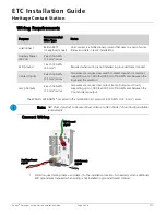
5:
Connect Contact Input (Switch) wiring to the five-position connector labeled for Contact Inputs.
a: Strip 1/4” (6 mm) from the ends of each Contact Input wire and the Ground wire that will
terminate to the five-position connector.
b: Strip 3/8” (9-10 mm) from the ends of each reference Ground wire to be bussed into a WAGO
connector.
c: Loosen the terminal screw for each required termination and insert the wires into the
corresponding terminals. Tighten the screws firmly onto the wires.
d: Use a WAGO connector to bus the reference Ground wires. Open the terminal levers on the
WAGO connector and insert one wire per terminal, including a lead from the Contact Input
connector Ground terminal, then close the levers.
6:
Connect Lamp Output wiring to the five-position connector labeled Lamp Outputs.
a: Strip 1/4” (6 mm) from the ends of each Lamp Output wire and the V out wire that will terminate
to the five-position connector.
b: Strip 3/8” (9-10 mm) from the ends of each V out wire to be bussed into a WAGO connector.
c: Loosen the terminal screw for each required termination and insert the wires into the
corresponding terminals. Tighten the screws firmly onto the wires.
d: Use a WAGO connector to bus the V out wires. Open the terminal levers on the WAGO connector
and insert one wire per terminal, including a lead from the Lamp Outputs connector V out
terminal, then close the levers.
7:
Attach the station to the installation location.
Note:
Plan your wiring accordingly.
Only one Ground (common) terminal is provided on the Contact Input connector. If
multiple switch inputs are required for your installation, additional reference Ground
connections must be bussed together using a WAGO connector.
Note:
The lamp voltage conducts from “V” to the lamp outputs. Connect the anode to the “V”
and the cathode to the lamp output connection.
Note:
Plan your wiring accordingly.
Only one Voltage out (V) terminal is provided on the Lamp Outputs connector. If multiple
lamp outputs are required for your installation, additional V out connections must be
bussed together using a WAGO connector.
Note:
The Paradigm Architectural Control Processor (P-ACP) to which this Heritage station is
connected must learn, or be told, the station hardware address (a.k.a. neuron ID). This
ID can be manually entered into the configuration (as labeled on the front of the station)
using LightDesigner software, or can be identified by the connected Paradigm ACP using
the “Connect a Device” menu.
Reference the Unison Paradigm Architectural Control Processor Configuration Manual;
specifically the section on Arch Setup Menu, LonWorks Connections.