


2
The Retrofit
5
S e c t i o n 2
The Retrofit
Preparation
Step 1:
Use Sensor Configuration Editor and a SLTA to download and save the current
Sensor configuration out of racks for later reference.
Step 2:
Turn off the main breaker and disconnect all of the Cam-Lok® connectors from
the touring rack.
Step 3:
Pull the modules out of the rack. Note and document the module’s
order/positioning in the rack for proper insertion and configuration later.
Step 4:
Use a digital voltmeter and VERIFY that power is off by checking voltages for all
combinations between the phase bars, neutral and ground.
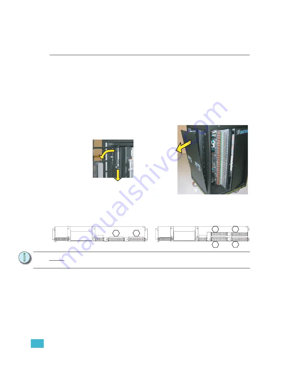
Step 5:
Remove the rack door in front of the CEM
by pushing down on the tab in top hinged
corner.
Step 6:
Remove the left side of the touring rack
(10 Phillips head screws) and set it aside.
Remove the Old
Step 1:
Unscrew the dimmer output edge connectors from the backplane metal.
Step 2:
Carefully feed the dimmer output ribbon cables through the backplane
individually. As you remove the ribbon cables, mark them with a permanent
marker them as illustrated above in the hexagons. There may be stickers on the
ribbon cables already, however these refer to cable length and not dimmer
outputs. They should not be used as a reference to these instructions.
Step 3:
Examine each ribbon cable for any nicks or cuts due to backplane scrapes.
Step 4:
Unscrew and remove the control data cable connector (J3) from the backplane
and feed it through the metal work.
Step 5:
Unscrew the power edge connector (J1). Remove it from the backplane by
sliding it out of the notch in the rack and carefully pushing it through the
N o t e :
The order/layout of the dimmer output edge connectors is different on the CEM+
backplane.
Remo
ve
1-
P
u
s
h
2
-R
em
ove
CEM SP48 Ribbon Cable Layout
(1-24)
(73-96)
(49-72)
(25-48)
1
3
4
2
(25-48)
(1-24)
CEM SP24 Ribbon Cable Layout
1
2
J1
J3
J1
J3
Summary of Contents for sensor+ CEM+
Page 15: ......


