background image

Fixture Overview

7

Modular Control

Note:

Some consoles may refer to the Flex effects by the feature name "Macro". For

the purposes of the SolaPix 7 software and user manual, "Flex" and "Macro" are
interchangeable.

The SolaPix 7 fixture has three segments of control (or modules) that essentially give you three
fixtures in one, letting you customize each fixture based on your control needs.

The Base module is the master. The settings in this module control the basic functions of
the fixture, which include pan, tilt, zoom, and the control settings for the fixture.

The Flex module lets you build and customize animation effects based on a library of
animations.

The Pixel module gives you individual control of each pixel.

The Base module is always active. The Flex and Pixel modules can be disabled, or they can be
set to Compound or Independent modes.

In Compound mode, a module automatically addresses itself to the same source as the Base
module and follows immediately after the address of the Base module.

In Independent mode, you address a module individually to any source (DMX or Ethernet),
Address, or Universe that your control setup requires.

Compounding the modules enables several different options:

Base + Flex (default)

Base + Pixel

Base + Flex + Pixel

See

Configure the Fixture on page 16

for information about configuring the modules.

Because the modules all control the same light sources, you can set the priority of control using
the Module Priority function (channel 12 in the Base module).

See the SolaPix 7 DMX channel map on the ETC website for details:

etcconnect.com/Products/High-End-Systems/Lighting-Fixtures/SolaPix/Documentation.aspx

Summary of Contents for High End Systems SolaPix 7

Page 1: ...High End Systems SolaPix 7 Automated Luminaire User Manual Version 1 2 9 Part Number 2594M1200 1 2 9 Rev D Released 2021 03 ...

Page 2: ...arks both marked and not marked are the property of their respective owners You can find complete High End Systems terms and conditions and warranty information at etcconnect com Support Warranty aspx ETC intends this document whether printed or electronic to be provided in its entirety ...

Page 3: ... Use Guidelines 5 Fixture Overview 6 Modular Control 7 Install the Fixture 8 Power 11 Input and Power Factor 11 Connector Specification 11 DMX Control 12 DMX Connector Pinout 12 Connect DMX Cables to Fixture 12 Terminate DMX 13 Set the DMX Start Address 13 DMX Channels 13 Ethernet Control 14 Connect Ethernet Cables to a Fixture 14 Set the DMX Start Address 15 ...

Page 4: ...the User Interface 16 Set Fixture Parameters 17 Address 17 Info Menu 21 Set Menu 23 Test Menu 26 Preset Menu 26 Error Codes 27 Maintenance 28 Clean the Fixture 28 Replace the Fuse 28 Compliance 29 FCC Part 15 Class A 29 Declarations of Conformity 30 ii SolaPix 7 User Manual ...

Page 5: ...sages Note Notes are helpful hints and information that is supplemental to the main text CAUTION Hot Surfaces This statement indicates that while operating equipment surfaces may reach very high temperatures Allow the fixture to cool before handling or servicing CAUTION A Caution statement indicates situations where there may be undefined or unwanted consequences of an action potential for data lo...

Page 6: ...ddleton WI 53562 800 775 4382 USA toll free 1 608 831 4116 service etcconnect com ETC GmbH Germany Austria Switzerland Eastern Europe and Russia Technical Services Department Ohmstrasse 3 83607 Holzkirchen Germany 49 80 24 47 00 0 techserv germany etcconnect com ETC Austin High End Systems Products Technical Services Department 2105 Gracy Farms Lane Austin TX 78758 USA 800 890 8989 USA toll free 1...

Page 7: ...oit pas être jeté avec les déchets ménagers mais doit être déposé dans une collecte de déchets électroniques ou dans un point de collecte Operate indoors only not where this product would be exposed to the weather Ne fonctionne qu à l intérieur pas là où ce produit serait exposé aux intempéries WARNING Note the following safety warnings before use This equipment is designed for operation by qualif...

Page 8: ... et les matériaux combustibles 0 1 m 4 0 in Distance minimale avec les objets éclairés 1 0 m 3 28 ft WARNING RISK OF ELECTRIC SHOCK Do not operate this device with the cover open Disconnect the fixture from power and DMX and allow it to cool before performing any cleaning and maintenance AVERTISSEMENT RISQUE DE CHOC ÉLÉCTRIQUE N utilisez pas cet appareil avec le couvercle ouvert Débrancher la lamp...

Page 9: ... yourself with its functions Do not permit persons who are not qualified and familiar with its functions to operate the fixture Do not modify the fixture Any modifications will void the warranty This manual describes the proper installation and operation of this fixture Using this fixture in any way other than the intended use may cause damage and void the warranty When the fixture has been stored...

Page 10: ...ix 7 fixture see the technical data sheet etcconnect com Products High End Systems Lighting Fixtures SolaPix Documentation aspx 2 3 4 5 1 7 8 9 10 11 6 1 Lens 2 Tilt lock 3 Display 4 Navigation controls 5 Pan lock 6 Ethernet ports x2 7 DMX Thru 8 DMX In 9 Power In 10 USB 11 Power Out ...

Page 11: ...Base module is always active The Flex and Pixel modules can be disabled or they can be set to Compound or Independent modes In Compound mode a module automatically addresses itself to the same source as the Base module and follows immediately after the address of the Base module In Independent mode you address a module individually to any source DMX or Ethernet Address or Universe that your contro...

Page 12: ...fied personnel AVERTISSEMENT Boîtier NEMA de type 1 utilisation en intérieur emplacements secs uniquement Ne l utilisez pas en extérieur Ce projecteur est conçu pour être utilisé dans des environnements où l humidité ne dépasse pas 90 sans condensation L emplacement d installation doit supporter une charge concentrée minimale de 10 fois le poids de l appareil L installation doit toujours être sécu...

Page 13: ...n The installation must only be carried out by qualified personnel ATTENTION Respectez tous les règlements locaux et toutes les pratiques recommandées par l autorité compétente L installation doit être effectuée uniquement par du personnel qualifié You can install the fixture in any of the orientations shown below ...

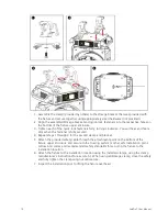
Page 14: ...ully secured 4 Repeat steps 1 through 3 for the second clamp and bracket 5 Attach the provided safety cable through the attachment point on the bottom of the fixture upper enclosure and secure to the trussing system or other safe installation point Follow local codes and recommended safety standards for securing the fixture to the installation location 6 Attach the fixture to the installation loca...

Page 15: ...lug with integral cord grip that is within the voltage and amperage rating of this luminaire AVERTISSEMENT Risque de choc et d incendie Assurez vous d utiliser une prise de mise à la terre avec décharge de traction intégrée qui respecte la tension et l ampérage de ce luminaire A power input cable with powerCON TRUE1 TOP input to bare ends is provided The power input cable is rated for maximum 20 A...

Page 16: ...ocket connector on one end and a XLR plug connector on the other end Terminate the cable ends as indicated in the pinout image below Connect DMX Cables to Fixture The following instructions are guidelines for connecting DMX to your fixture Your installation may vary 1 Connect the XLR plug connector of a DMX data cable to the DMX Thru connector on the DMX control source 2 Connect the XLR socket con...

Page 17: ...ber from which the fixture starts to listen to the digital control information sent out from the control source Modify the fixture DMX start address on the user interface located on the upper enclosure See Address on page 17 Example The SolaPix 7 requires up to 66 channels of control depending on the configuration of the modules The Base module uses 21 channels When the Flex module is set to Compo...

Page 18: ... Ethernet control source to one of the Ethernet ports on the first fixture in the Ethernet control run 2 Connect the first fixture to a second fixture by connecting a cable from the second Ethernet port on the first fixture to one of the Ethernet ports on the second fixture 3 Continue linking the remaining fixtures by connecting a cable from Ethernet port to Ethernet port on the fixtures on the co...

Page 19: ...s up to 66 channels of control depending on the configuration of the modules The Base module uses 21 channels When the Flex module is set to Compound mode an additional 17 channels are added If the Pixel module is also set to Compound mode then an additional 28 channels are added making 66 channels total If you are using the Base and Pixel modules the Pixel module is set to Compound mode and the F...

Page 20: ... three seconds to access the main menu 2 Browse the menu by pressing the up down left or right navigation buttons 3 Press the Enter button to select a menu item 4 Modify the selection by pressing the up down left or right navigation buttons according to the selection 5 Press the Enter button to confirm a modified selection 6 To exit the menu press the MODE ESC Mode Esc button Note If you press the...

Page 21: ...l You can configure each module individually or you can compound some or all of the modules For information about the modules see Modular Control on page 7 Note Some consoles may refer to the Flex effects by the feature name Macro For the purposes of the SolaPix 7 software and user manual Flex and Macro are interchangeable Navigate Main Menu Address Base Module Base module configuration is mandato...

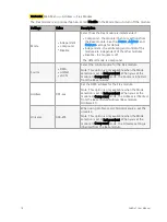
Page 22: ...MX Art Net sACN Select the control source for the Flex module Note This option is only available when the Mode selection is set to Independent When you set the module to Compound mode the Source is inherited from the Base module Address 001 xxx Set the DMX address for the Flex module Note This option is only available when the Mode selection is set to Independent When you set the module to Compoun...

Page 23: ...on is only available when the Mode selection is set to Independent When you set the module to Compound mode the Source is inherited from the Flex module or the Base module if the Flex module is disabled Address 001 xxx Set the DMX address for the Pixel module Note This option is only available when the Mode selection is set to Independent When you set the module to Compound mode the Address is inh...

Page 24: ...ce and a unique address Set both the Flex and Pixel modules to Compound mode The result All fixtures have 66 channels of control for Base module functions animations and pixels The recommended console library is Base Flex Pixel Limited Universes of DMX with Individual Control The system does not have enough DMX to dedicate 38 channels of DMX to each fixture but individual control of each fixture i...

Page 25: ...running time of the device shown in hours h Last Run Hrs XXXX Hours Running time of the fixture from the last time that the run time value was reset shown in hours h LED Hours XXXX Hours Total running time of the fixture LEDs shown in hours h Timer PIN Timer PIN XXX You must enter the Timer PIN in order to access the Clr Last Run menu item The default Timer PIN is 038 Clr Last Run ON OFF This pass...

Page 26: ...ture temperature as read from the fixture head near the CMY filter View Power Temperature Navigate Main Menu Info Power Temp Displays the current temperature as read from the power supply in the fixture base which can help you to determine if the power supply is overheating View Fan Speeds Navigate Main Menu Info Fan Speed Displays the speeds of the fixture s fans in RPM View Ethernet IP Address N...

Page 27: ...per motors to power off when the fixture loses DMX control signal for a set period of time The default time setting is 15 minutes Refresh Rate 2 4 kHz 16 kHz Set the refresh rate of the fixture The 16 kHz setting is quieter than the 2 4 kHz setting and creates a beam that does not flicker when shown on camera The 2 4 kHz setting prioritizes flawless stepless dimming P T Home Mode Standard Tilt Fir...

Page 28: ...t IP XXX XXX XXX XXX This password protected menu item lets you modify the IP address You must enter the Service PIN to access this menu item The default IP address is 002 142 058 034 Ethernet Mask IP XXX XXX XXX XXX This password protected menu item lets you modify the IP subnet mask You must enter the Service PIN to access this menu item The default IP subnet mask is 255 000 000 000 Clr Err Info...

Page 29: ...u Set USB Update Fixture firmware updates are available on the ETC website at etcconnect com Products Live Events 1 Save the firmware update file to a USB drive 2 Insert the USB drive in the fixture base see Fixture Overview on page 6 for the USB port location 3 On the Main Menu select Set USB Update The fixture reads the USB drive and displays a list of any firmware update files on the USB drive ...

Page 30: ... Select an individual channel on the fixture and manually set the channel value While in Manual Control mode all effects are canceled the shutter opens and the dimmer intensity is set to 100 Re Calibrate an Individual Feature Navigate Main Menu Test Calibration Please contact Technical Services before using this parameter See Help from Technical Services on page 2 You must enter the Calibration PI...

Page 31: ... magnetic indexing circuit malfunctions optical or magnetic sensor failure the stepper motor is defective or the related IC driver on the main PCB has failed the Pan movement is not located in the default position after the reset Tilt This message displays after the reset of the fixture if any of the following conditions exist the fixture head magnetic indexing circuit malfunctions optical or magn...

Page 32: ... not fail prematurely regular maintenance is recommended Clean the Fixture CAUTION The backside of each lens in the SolaPix 7 fixture is coated with a HazeFree lens coating technology patent pending that keeps the lens clear when the fixture is used with theatrical haze Use of paper toweling or other abrasive high friction wipes and ammonia based glass cleaners may permanently damage the coating I...

Page 33: ...ed operation Note This equipment has been tested and found to comply with the limits for a Class A digital device pursuant to Part 15 of the FCC rules These limits are designed to provide reasonable protection against harmful interference when the equipment is operated in a commercial environment This equipment generates uses and can radiate radio frequency energy and if not installed and used in ...

Page 34: ...levision and film studios outdoor and indoor EN 61347 1 2015 Lamp controlgear General and safety requirements EN 62031 2008 A2 2015 LED modules for general ligh ng Safety specifica ons EN 61347 2 13 2014 A1 2017 Lamp controlgear Par cular requirements for d c or a c supplied electronic controlgear for LED modules Electromagne c Compa bility Direc ve EMCD 2014 30 EU EN 55015 2013 A1 2015 Limits and m...

Page 35: ... A1 2017 Lamp controlgear Par cular requirements for d c or a c supplied electronic controlgear for LED modules Electromagne c Compa bility Direc ve EMCD 2014 30 EU EN 55015 2013 A1 2015 Limits and methods of measurement of radio disturbance characteris cs of electrical ligh ng and similar equipment EN 61547 2009 Equipment for general ligh ng purposes EMC immunity requirements EN 61000 3 2 2014 El...

Page 36: ...re New York NY Orlando FL Los Angeles CA Austin TX Web etcconnect com Support support etcconnect com Contact etcconnect com contactETC 2021 ETC Inc Trademark and patent info etcconnect com ip Product information and specifications subject to change ETC intends this document to be provided in its entirety 2594M1200 1 2 9 Rev D Released 2021 03 ...

Reviews: