

ETC Setup Guide
ERn Ethernet Switch Module
ERn Ethernet Switch Module
Page 2 of 3
ETC
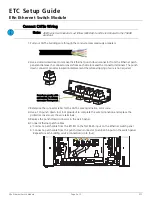
Connect CAT5e Wiring
1: Pull your CAT5e building wire through the conduit access previously prepared.
2: Use a slotted screwdriver to remove the Ethernet punch down connector from the Ethernet patch
panel and remove the connector covers from each side to reveal the connector terminals. The punch
down connector provides insulation displacement therefore stripping of wire is not required.
3: Reference the connector label for the CAT5e wire termination color code.
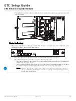
4: Use a 110 punch down tool (not provided) to complete the wire termination and replace the
protective covers over the wire terminals.
5: Replace the punch down connector in the patch panel.
6: Connect Ethernet patch cables.
a: Connect a patch cable from the left I/O to the first RJ-45 input on the Ethernet switch panel.
b: Connect a patch cable from the punch down connector to an RJ-45 input on the switch panel.
Repeat for each building service connection (up to four).
Note:
All Ethernet terminations must follow IEEE 802.3 and be terminated to the T568B
standard.
Press here gently with
screwdriver to release
connector from panel.