


ETAS
Hardware Description
ES582.1 - User’s Guide
13
3.4
Interfaces
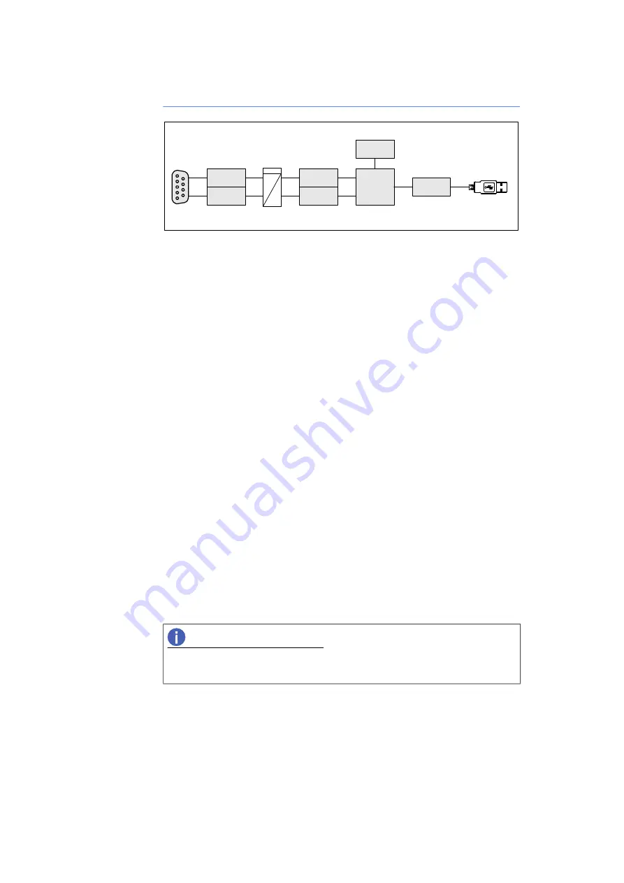
Fig. 3
-
2
ES582.1 Block Diagram
3.4.1
CAN Interfaces (CAN1/CAN2)
CAN FD (CAN Flexible Data Rate) is an improved, downward-compatible CAN
protocol. The main differences to CAN are in the extension of the user data per
message from 8 to 64 bytes, higher transmission rates of up to 8 Mbit/s and
longer checksums, which increase the reliability of the transmission. CAN FD
covers the demand for higher bandwidth for networks in the automotive indus
-
try. At the same time, CAN FD nodes can easily be integrated into the existing
CAN infrastructure.
The ES582.1 CAN FD Bus Interface USB Module features the CAN interfaces
CAN1 and CAN2 at the 9-pin socket. The two CAN interfaces are independent
CAN channels with separate CAN controllers. Tye are isolated from the USB
port of the ES582.1.
Operating modes
Each CAN interface can optionally be operated in the CAN high-speed operat
-
ing mode or in the CAN FD (CAN Flexible Data Rate) operating mode. The
ES582.1 module supports ISO-compliant CAN FD as well as non-ISO-compliant
CAN FD.
The interfaces CAN1 and CAN2 can be configured independently of each other
in the application software for the following operating modes:
• CAN
• ISO-compliant CAN FD
• Non-ISO-compliant CAN FD
Multi-client support
Each of the CAN channels of the module ES582.1 can support two clients
(application tools) at the same time. On each of the CAN channels, simultane
-
ous access, e.g. by an application tool (e.g. INCA) and a diagnostics tool (e.g.
DiagRa) is possible.
Overall, each individual ES582.1 module connected to the PC can operate four
(different) clients or application tools.
NOTE
The two interfaces CAN1 and CAN2 can be used independently of each other
in different operating modes.
bpRUOKN
CAN1
CAN2
CAN FD
Transceiver
CAN
/
CAN FD
Controller
CAN FD
Transceiver
CAN
/
CAN FD
Controller
Microcontroller
LED
USB Interface
Isolation
USB 2.0