ET Enterprises HVLAB3000 Instruction Manual Download Page 7

page 7 of 14 

Connect the HVLAB3000 to a spare USB port on your computer.

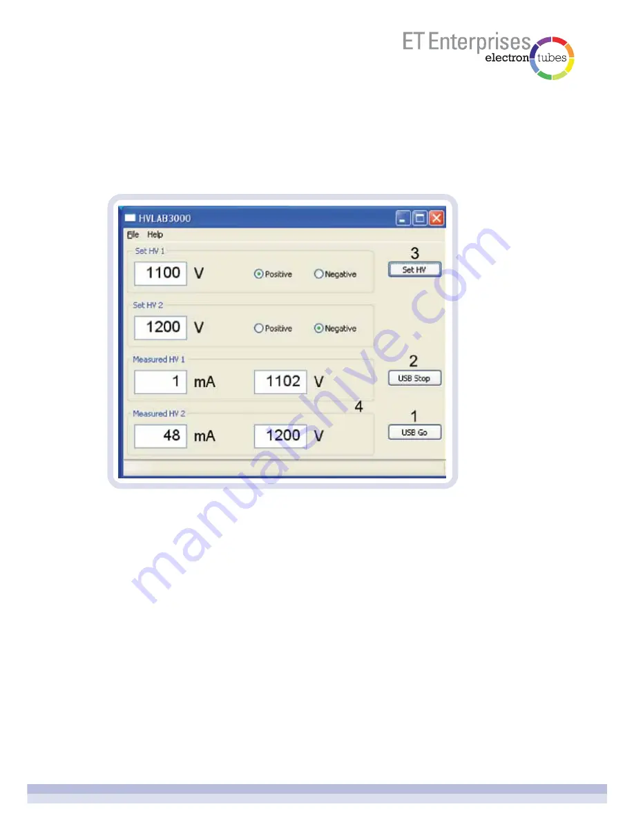
Open the HVLAB3000 Windows application.

6.4.1.1  USB Go

Press the USB Go button to enter USB remote control. The HVLAB3000 front panel 

controls will be locked out and the front panel remote control LED will light and the high 

voltage will switch on. If the high voltage was on when the USB Go button was pressed, it 

will remain on at that voltage. If the HV output was off when the USB Go button was 

pressed, the high voltage will switch on at near zero output.

6.4.1.2  USB Stop

Press the USB Stop button to leave USB remote control mode. The high voltage output will 

be switched off and the remote control LED will switch off. Normal control will return to the 

HVLAB3000 front panel.

6.4.1.3  set HV

Enter the desired high voltage and select the polarity using the radio buttons. The high 

voltage will change when the SET HV button is pressed. It may take several seconds for 

the high voltage output to settle to its new value.

6.4  remote control

6.4.1  USB control - the Windows application

Summary of Contents for HVLAB3000

Page 1: ...n is assumed for future manufacture While every effort is made to ensure accuracy of published information the company cannot be held responsible for errors or consequences arising therefrom an ISO 90...

Page 2: ...HVLAB3000 bench top high voltage power supply page 2 of 14 Introduction Installing the software Basic system Front panel Rear panel Using the HVLAB3000 Calibration 1 2 3 4 5 6 7 3 3 3 4 5 6 11...

Page 3: ...rd will guide you through the setup process The software is installed in C ETEL BenchTopHV Shortcuts to the various applications are installed on your desktop and in the HVLAB3000 program group in you...

Page 4: ...rity The button will only operate when the high voltage output is switched off The polarity LEDs display the polarity selected Each polarity has its own rear panel connector Only one polarity output m...

Page 5: ...the front panel high voltage control This operates both positive and negative outputs 4 high voltage limit adjustment 8 USB connector The HVLAB3000 can be controlled remotely using USB and the bench t...

Page 6: ...g method is not applicable with very low current loads CAUTION the power input switch must be off before connecting or disconnecting HV cables Each polarity has its own current limit adjustment which...

Page 7: ...output was off when the USB Go button was pressed the high voltage will switch on at near zero output 6 4 1 2 USB Stop Press the USB Stop button to leave USB remote control mode The high voltage outp...

Page 8: ...4 1 5 open output file Opens the output file in Notepad 6 4 1 6 find USB devices If the HVLAB3000 is connected to the computer s USB port after opening the Windows application use Find USB Devices to...

Page 9: ...3000 is in USB control mode 6 4 2 USB control the Excel spreadsheet The Excel spreadsheet is a modification of the MCS CT3 spreadsheet please see the MCS CT3 user manual for more information The HVLAB...

Page 10: ...6 4 2 2 MCS CT3 windows Excel application This application starts automatically when you open the MCS CT3 HVLAB3000 Excel Control xlsm spreadsheet It acts as the interface between Excel and the MCS CT...

Page 11: ...en the application is closed or the computer is switched off Please see the MCS CT3 user manual for more information about the MCS CT3 6 4 3 external voltage control When the remote control input swit...

Page 12: ...he rear panel High Voltage Limit and the Positive and Negative Current Limit adjustment potentiometers fully clockwise This will remove the voltage and current limits 2 Connect the mains supply and sw...

Page 13: ...at steps 4 5 and 6 for each calibration voltage The last calibration voltage is about 3100 V 8 Press the calibration button The HVLAB3000 will save the calibration factors in internal memory and exit...

Page 14: ...n the front panel voltage display Use the front panel HV control to adjust the actual output voltage shown on the volt meter until it agrees with the front panel display 7 Press the calibration button...

Reviews: