Summa Series Servodrive Product Manual
Application Functions
Document Version: V1.01
(Dec, 2019)
© 2019 ESTUN Automation Co., Ltd. All right reserved.
7-11
7.7.3
Encoder Divided Pulse Output
Encoder Divided Pulse Output Signals
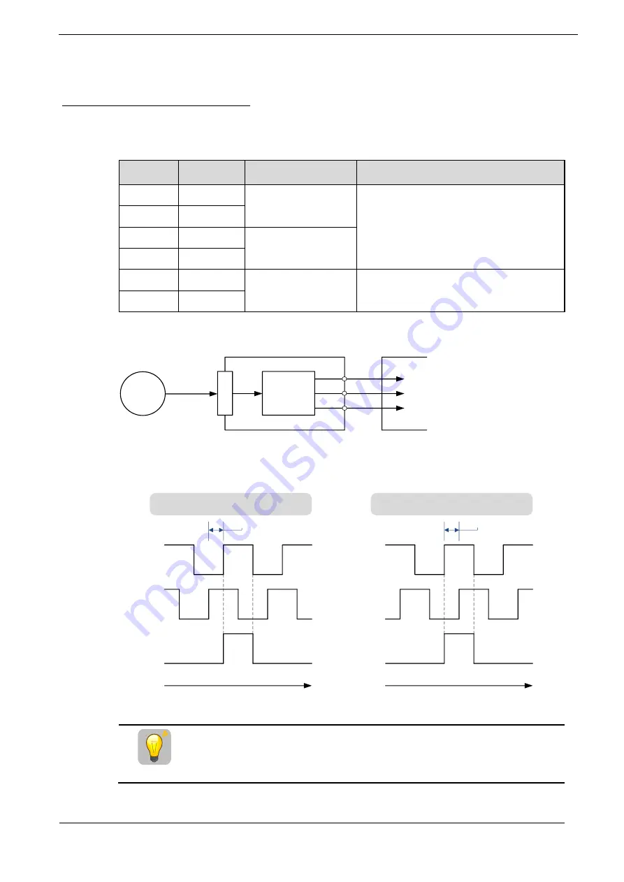
The encoder divided pulse output is a signal that is output from the encoder and processed inside the
Drive. It is then output externally in the form of two phase pulse signals (phases A and B) with a 90°
phase differential. At the host controller, it is used as the position feedback.
Signal
Pin
Name
Remarks
PAO+
CN1-21
Encoder Divided Pulse
Output, Phase A
These encoder divided pulse output pins
output the number of pulses per Motor
resolution that is set in Pn200 (Pulse Numbers
for PG Frequency Division). The phase
difference between phase A and phase B is an
electric angle of 90°.
PAO-
CN1-22
PBO+
CN1-23
Encoder Divided Pulse
Output, Phase B
PBO-
CN1-24
PCO+
CN1-25
Encoder Divided Pulse
Output, Phase C
These pins output one pulse every Motor
rotation.
PCO-
CN1-26
ENC
Dividing
circuit
Serial data
Host contoller
Drive
PAO
PBO
PCO
CN2
CN1
NOTE
: Even for reverse operation (Pn001.0=1), the output phase form is the same as shown above.
The output phase form is as shown in Figure 7-2.
Figure 7-2
Output phase form
Forward rotation or movement
(phase B leads by 90°)
Phase A
t
90°
t
90°
Reverse rotation or movement
(phase A leads by 90°)
Phase B
Phase C
Phase A
Phase B
Phase C
IMPORTANT
If you use the Drive’s Phase-C pulse output for an origin return, rotate
the Motor two or more rotations before you start an origin return.
If an external encoder is used for the divided pulse output, the setting is
the same as above.


