


CHAPTER 3
STARTING OUT
Revised: 16 Oct 03
3-2
EST P/N AA107
MODEL 192E ESTeem CONFIGURATION
The following steps should be completed before any modifications are made to the network operating parameters for the
ESTeem Model 192E.
1.
Connect the antenna to the antenna connector on the ESTeem Model 192E (Figure 2).
2.
When powering up the ESTeem for the first time you must use the ESTeem RS-232C Configuration Menu to setup the basic
operating parameters such as assigning the IP Address, IP Net Mask, Gateway IP Address, Domain Name, and DNS IP
Address.
3.
Connect the serial cable (EST P/N: AA062) between the RS-232 connector on the ESTeem to the serial port on the computer.
4.
Any terminal emulation program can be used for the configuration of the ESTeem. Most Windows users use Hyper
Terminal. Configure your RS-232C port for a Baud Rate to 38,400, Data Bits to 8, Parity to None, Stop Bits to 1 and
Handshaking to None. For information on the Model 192E RS-232 Port see Appendix C.
5.
Plug the ESTeem Model AA174 power supply into a wall socket and connect the Molex power connector to the ESTeem.
The power light (PWR) on the front of the ESTeem should be illuminated.
6.
If your computer is configured properly, you will see the ESTeem Model 192E booting sequence on your Terminal Emulation
program. See Figure 3.
Once the ESTeem boot sequence is complete (approximately 1 minute) you will receive this message:
“Please press Enter to active this console.”
If you don’t see this message press the Reset button on the front panel of the ESTeem and/or check the programming of
your RS-232 port.
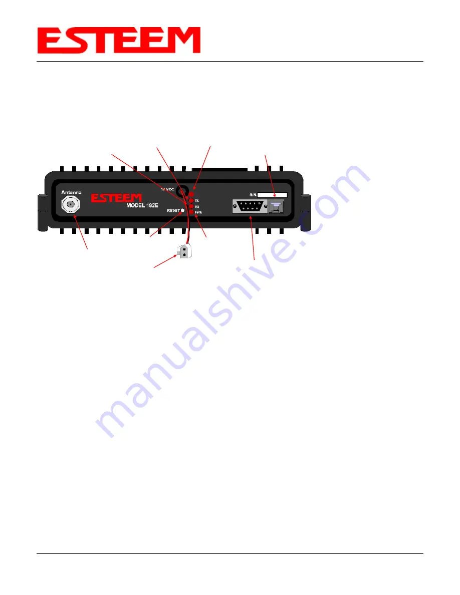
Antenna Connector
(TNC-R)
12 VDC Input
Power Connector
(2 Pin Molex)
Reset Switch
RS-232
Programming Port
(9 Pin DB Connector)
RJ-45 10BaseT
Ethernet Port
Power LED
Transmit LED
Receive LED
T/E LED
T/E
Figure 2: Model 192E Front Panel Description
Notes:
•
Configure the Model
192E prior to
mounting.
•
Some of the following
steps, such as
connecting the serial
cable, are easier to
perform if the
ESTeem is accessible.
•
Please attach an
antenna to the Model
192E before power up.
•
There is no Power
On/Off switch on the
Model 192E.
Summary of Contents for MODEL 192E
Page 20: ...CHAPTER 3 STARTING OUT Revised 16 Oct 03 3 5 EST P N AA107 Figure 6 Ethonly Screen...
Page 40: ......
Page 59: ...CHAPTER 7 ANTENNA SETUPS Revised 15 Mar 04 7 4 EST P N AA107...
Page 60: ...CHAPTER 7 ANTENNA SETUPS Revised 15 Mar 04 7 5 EST P N AA107...
Page 61: ...CHAPTER 7 ANTENNA SETUPS Revised 15 Mar 04 7 6 EST P N AA107...
Page 62: ...CHAPTER 7 ANTENNA SETUPS Revised 15 Mar 04 7 7 EST P N AA107...
Page 63: ...CHAPTER 7 ANTENNA SETUPS Revised 15 Mar 04 7 8 EST P N AA107...
Page 78: ......
Page 88: ......