background image

USER MANUAL > USE OF THE TRACER

TESS > V4 - 01.17

47

3

2

1

3

2

1

3

2

1

3

2

1

3

2

1

3

2

1

3

2

1

3

2

1

3

2

1

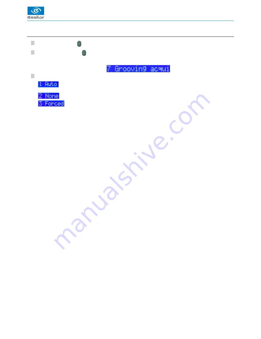
c. Groove acquisition settings

Press simultaneously on 

 and “1”.

Press on “7”, then press on 

 to access the “Grooving acquisition” menu.

Choose among the 3 modes of groove acquisition:

: if the thickness of the frame is less than 3.5 mm, the frame is detected as metal. Groove acquisition is then

automatically triggered.

: Groove detection is never performed.

: Groove detection is performed in every case.

The display indicates:

>

Summary of Contents for TESS

Page 1: ...User Manual...

Page 2: ......

Page 3: ...dger Delta T Jess JessIE JessD 18 c Login with a Delta 2 edger 19 4 Tracer description 20 5 Presentation of the internal menu 21 6 Connection configuration 21 a Configuration of protocols 22 b Configu...

Page 4: ...CONTENTS 1 Calibration test 53 2 Calibration 54 3 Autotest 55 VII IMPORT EXPORT 57 1 Export 59 2 Import 60 a Addition of a gauge 60 b Software update 61 VIII ERROR CODES BARCODES 63 1 Error codes 65 2...

Page 5: ...I INTRODUCTION...

Page 6: ...USER MANUAL INTRODUCTION 6 TESS V4 01 17...

Page 7: ...silor will be held responsible the possible loss of data or malfunctions which could result from these errors or omissions 2 Warning To reduce the risks related to the use of electrical equipment fire...

Page 8: ...USER MANUAL INTRODUCTION 8 TESS V4 01 17...

Page 9: ...II PRECAUTIONS REQUIRED...

Page 10: ...USER MANUAL PRECAUTIONS REQUIRED 10 TESS V4 01 17...

Page 11: ...o direct sunlight away from any heat sources away from any strong magnetic fields away from any corrosive chemical products or vapors and liquids Make sure to arrange it so it can expel heat from the...

Page 12: ...cer except for the feeler using a soft rag dampened with water or a neutral detergent dish soap To prevent dust deposits from disturbing the high precision of the tracer we advise that you close the p...

Page 13: ...III INSTALLATION...

Page 14: ...USER MANUAL INSTALLATION 14 TESS V4 01 17...

Page 15: ...ng of a pattern or a lens demo or already cut Automatic measurement of the bridge of the frame in binocular tracing Frame thickness measurement Differential tightening of the clamps RS232 port and RJ...

Page 16: ...ies first Take out the product with its two foam supports Remove the foam supports Save all the packaging for possible re use b Unbinding of the device Before any use it is that you remove the transpo...

Page 17: ...ll cause a warning message to appear the next time the machine is started d Packing of the device To pack the tracer Turn off the device It is also possible to use the barcodes below it is also possib...

Page 18: ...he network to which the tracer will be connected b Connection to an Essilor edger Delta T Jess JessIE JessD The connection of the tracer to the edger will be carried out with the two devices powered o...

Page 19: ...e two installations described above c Login with a Delta 2 edger Connect the RJ 45 cable of the tracer to the edger Then to the tracer Press simultaneously on and 1 Press on 6 Communicate then press o...

Page 20: ...Protective cover Two line display Tightening clamps Tracing centering Feeler Selection RE LE RLE Precal lenses order cycle selection Very high base frame cycle selection Calibration test launch Traci...

Page 21: ...1 to 9 then press on data exchange with an external USB key For more information consult the section Import export p 57 deletion of information from the tracer enter the desired value from 1 to 9 then...

Page 22: ...connection OMA protocol with Ethernet connection PCCom protocol for Opsys V1 specific Japan protocol Enter the selected line number selected then press on to confirm Press on to exit the menu To confi...

Page 23: ...n 3 then press on to make your choice Then choose the desired protocol by navigating the menu using the keys and by default mode connection with Iness Enter the selected line number selected then pres...

Page 24: ...ion Opsys configuration Edger port 19200 Inspection Configuration Delta T Any modification of this configuration could harm the proper performance of the instruments We advise that you modify the conf...

Page 25: ...on 2 then press on to choose the flow test no equipment flow test usual configuration activated equipment flow test Configure the edger port Press on 2 then press on If the choice on line 1 does not c...

Page 26: ...ing via DHCP server menu not used static IP addressing Enter the chosen line number selected then press on Press on to exit the menu IP address If the address indicated does not correspond to your con...

Page 27: ...IV CHECK PRO...

Page 28: ...USER MANUAL CHECK PRO 28 TESS V4 01 17...

Page 29: ...r Perform an autotest from the computer Perform a calibration inspection from a computer Perform calibrations from a computer Personalize the display of the tracer function not currently available Che...

Page 30: ...tracer Click on then on checkPro OK Click on and follow the various steps of installation Next Click on Finish The following window is displayed The installation starts The following window is displa...

Page 31: ...1 2 1 2 Instructions for use Click on the desktop icon and select the desired language Configure the desired properties and click on OK From this screen all the functions are accessible through the va...

Page 32: ...ration To configure the login between the tracer and the computer click on Port On the left side of the window you can activate the communication via serial port remember to configure the tracer in th...

Page 33: ...les Number of asymmetrical binocular cycles Number of RE monocular cycles Number of LE monocular cycles Number of very high base cycles Number of pattern cycles Number of calibrations Number of calibr...

Page 34: ...PRO 34 TESS V4 01 17 2 1 2 1 2 1 2 1 2 1 2 1 1 2 c Error message Click on List of recorded technician errors List of recorded optician errors Click on to return to the previous screen The following wi...

Page 35: ...rding to the selected login mode Display on the main screen the list of tracer choices then choose the port which the tracer is connected to COM3 for example Click on Tess serial number Tess memory ve...

Page 36: ...caliber Position stably the frame gauge within the tracing boundary on the 4 lower studs The V must be open aiming up Click on to validate Check the sizing number on the display of the tracer Press o...

Page 37: ...erform a calibration For more information consult the section error codes barcodes error codes p 65 Click on to return to the previous screen then press to confirm the tracer code 2 Test OK You can us...

Page 38: ...ing with the gauge caliber used Position stably the frame gauge within the tracing boundary on the 4 lower studs The V must be open aiming up Click on to validate Check the sizing number on the displa...

Page 39: ...error codes barcodes error codes p 65 Click on to return to the previous screen then press to confirm the tracer code 2 Calibration OK You can use of the tracer again your tracer s display is waiting...

Page 40: ...USER MANUAL CHECK PRO 40 TESS V4 01 17...

Page 41: ...V USE OF THE TRACER...

Page 42: ...USER MANUAL USE OF THE TRACER 42 TESS V4 01 17...

Page 43: ...ess on of the tracer to launch tracing Working on the current job allows for a simplified identification of the job between the tracer and the edger In this case the jobs are not memorized If you work...

Page 44: ...USER MANUAL USE OF THE TRACER 44 TESS V4 01 17 3 Frame tracing...

Page 45: ...left eye diode G L is lit 4 supports symmetrical binocular tracing the two diodes flicker In the case of a monocular tracing you will be asked to enter the value of the bridge at the end of the traci...

Page 46: ...d your job will not be memorized Press to confirm After the validation of the job number or current job press on to choose the adapted feeler insertion While carrying out 1 support choose low insertio...

Page 47: ...n and 1 Press on 7 then press on to access the Grooving acquisition menu Choose among the 3 modes of groove acquisition if the thickness of the frame is less than 3 5 mm the frame is detected as metal...

Page 48: ...specific cycle allows for the reading of very high base frames for which binocular tracing can be done only monocular purposes Activate this function when you want to read a very high base frame Choos...

Page 49: ...lding screw on the pattern holder tip Fix the pattern on the tip of the pattern holder nose to the right for a right lens and to the left for a left lens tip positioner of the pattern holder towards t...

Page 50: ...racing table so as to block the pattern holder Press on of the tracer to launch tracing The tracer automatically detects that it is a tracing pattern it asks you to select the tracing eye At the end o...

Page 51: ...VI AUTO MAINTENANCE...

Page 52: ...USER MANUAL AUTO MAINTENANCE 52 TESS V4 01 17...

Page 53: ...ection regularly Press on to select the calibration test function Select the gauge caliber number on the tracer then press on Position stably the frame gauge within the tracing boundary on the 4 lower...

Page 54: ...n provided with the tracer on the pattern holder nose towards the left Make sure that it is stable Then position the pattern holder within the tracing boundary For more information consult the section...

Page 55: ...rious movements of the tracer Press simultaneously on and 1 Select by pressing on 2 then on The tests starts T1 Jaws T2 Feeler reproducer T3 Rotation T4 Feeler transfer T5 Carriage transfer 1 Tests OK...

Page 56: ...USER MANUAL AUTO MAINTENANCE 56 TESS V4 01 17...

Page 57: ...VII IMPORT EXPORT...

Page 58: ...USER MANUAL IMPORT EXPORT 58 TESS V4 01 17...

Page 59: ...o transfer the information from the tracer to the USB key Three possible choices transfer of the data related to tracer piloting transfer of the data related to calibrations transfer of all the data F...

Page 60: ...173OD TXT and M66173OG TXT found on the root of the CD ROM and copy them to the root of the USB key The name of the files corresponds to the numbers of the gauges From the tracer Power up the tracer A...

Page 61: ...Select by pressing on 4 then press on Press on 2 then press on to transfer the information from the USB key to the tracer Select by pressing on 2 then press on Press on to confirm or on to cancel Rem...

Page 62: ...USER MANUAL IMPORT EXPORT 62 TESS V4 01 17...

Page 63: ...VIII ERROR CODES BARCODES...

Page 64: ...USER MANUAL ERROR CODES BARCODES 64 TESS V4 01 17...

Page 65: ...imes contact your technician Opt4006 Software error at the start up Restart the device If the error reoccurs several times contact your technician Opt4007 Software error in the task supervisor Restart...

Page 66: ...ob does not exist Opt6035 The gauge in the tracing table is not the correct one Insert the gauge pattern Opt6036 The gauge is absent or the gauge in the tracing table is not the correct one Insert the...

Page 67: ...USER MANUAL ERROR CODES BARCODES TESS V4 01 17 67...

Page 68: ...Essilor Instruments USA 8600 W Catalpa Avenue Suite 703 Chicago IL 60656 Phone 855 393 4647 Email info essilorinstrumentsusa com www essilorinstrumentsusa com...

Reviews: