background image

Essex Electronics, Inc. | 805.684.7601 | 800.KEY-LESS | fax 805.684.0232 | keyless.com

32

Warranty & Repairs

!

!

!

!

!

 Limited Lifetime Warranty

(effective date May 1, 2006)

Essex Electronics Inc.

 warrants that at the time of original

purchase from Essex Electronics Inc., the products specified below
are free from defects in workmanship and material. Subject to the
conditions and limitations set forth below, Essex Electronics Inc.
will, at its option, either repair or replace any part of its products
that prove defective by reason of improper workmanship or
materials. Repaired parts or replacement products will be provided
by Essex Electronics Inc. on an exchange basis, and will be either
new or refurbished to be functionally equivalent to new. Essex
Electronics Inc. reserves the right to discontinue a product for any
reason, without notice, at any time. If a product that has been
discontinued proves defective and if Essex Electronics Inc. is
unable to repair or replace the product, within the terms expressed
in this Limited Lifetime Warranty, a substitute product may be
provided at the Essex Electronics Inc.’s election, as a replacement
for the original discontinued product.

This Limited Lifetime Warranty extends only to the original retail or
wholesale Buyer and the original site of installation. It does not
cover any damage to this product or parts thereof, if the product is
installed in violation of the applicable codes or ordinances, or is
not installed in accordance with our installation instructions. This
warranty will only include the normal operating life of the LED’s
which will be 10 years from the date of the original sale. It does not
cover any damage that results from accident, abuse, misuse,
natural disaster, insufficient or excessive electrical supply, abnor-
mal mechanical or environmental conditions, or any unauthorized
disassembly, repair, or modification. This Limited Lifetime Warranty

○ ○ ○ ○ ○

Summary of Contents for Encoded Keyless Entry

Page 1: ...Essex Electronics Inc 805 684 7601 800 KEY LESS fax 805 684 0232 keyless com INSTALLATION INSTRUCTION MANUAL KPX 34 ERM3...

Page 2: ...n at any time Document Information IOMKPX34ERM Installation Operations Manual for the KPX 34 ERM3 Keypad with Encoded Relay Module ERM July 2006 This documentation is also applicable to prior revision...

Page 3: ...tors 10 Tamper Alarm 11 Encoded Relay Module LED Status Indicators 11 Operation Notes 11 Using the KPX 34 ERM3 with a PC 13 Connecting the KPX 34 ERM3 to a PC 13 Installing the CD ROM 13 Using Keypad...

Page 4: ...Essex Electronics Inc 805 684 7601 800 KEY LESS fax 805 684 0232 keyless com iii...

Page 5: ...yless Entry Access Control System is an extremely versatile 500 user code keyless entry system that combines an Essex Piezoelectric Keypad with HID Proximity and an Encoded Relay Module ERM K Prox wit...

Page 6: ...3 8 W x 7 16 D 13 x 8 6 x 1 1 cm Weight 16 oz 454 g Prox Reader Dimensions 7 1 4 H x 3 5 8 W x 1 3 16 D 18 4 x 9 2 x 3 0 cm Weight 10 3 oz 292 g 3x4 Keypad Dimensions 7 1 4 H x 3 5 8 W x 1 1 2 D Prox...

Page 7: ...tronic locking device or other equipment It may also be configured as a dry contact relay output to control a gate operator or garage door opener Set Door Open Time to 1 second The main output is prog...

Page 8: ...ontroller First key press or card presentation to the K Prox label area triggers a Timed Output 1 to 99 seconds 2 Auxiliary Output Manual Control or Timed Output 1 to 99 seconds 3 Third Door Users can...

Page 9: ...er opening If Output B is set up as Internal Alarm this switch will trigger the alarm if the door is opened without a code or if the door is left open longer than the Door Ajar Time setting RED BLACK...

Page 10: ...d both a code and a card can enter by using both In other words grounded is low level security only one form of ID is needed Not grounded is high level security two forms of ID are needed Security Lev...

Page 11: ...rrectly set 1 Remove power 2 Jumper the two pins above the connector labeled CONFIG 3 Apply appropriate power You should hear 4 beeps and the RED LED will flash and the GREEN LED will be solid 4 Now t...

Page 12: ...factory default settings are restored Keypad Reset In certain cases you may want to erase all user codes and restore system defaults To perform this procedure 1 Remove power 2 Jumper the two pins abov...

Page 13: ...y You should hear 3 beeps indicating successful configuration If you hear a long error beep re enter 98 followed by To change the audible beep proceed as follows Otherwise go to Step 6 To change the a...

Page 14: ...latched A solid red LED indicates that the door is locked Depending on how the System Options are configured User Commands are used to operate Manual Latching The User Commands are trailing digits en...

Page 15: ...RM and the Keypad and puts the Keypad into Programming Mode If no further programming is required press to exit If the ERM receives more than three 3 invalid EC s in a row the unit will go into LockUp...

Page 16: ...ly Upon the first attempt to send an ERM packet with a non matching EC the device will be put into the LockUp mode and from that point until a new EC is pro grammed the unit will essentially be shut d...

Page 17: ...PC Connect the ERM to a PC using a serial cable not included through the Serial COM Port The KPX 34 ERM3 is set for 9600 baud A serial to USB cable may also be used not included Installing the CD ROM...

Page 18: ...e in either protected or unprotected format and upload to the KPX 34 ERM3 If programming has been done at the Keypad you can download from the Keypad to a blank code chart names are not stored in the...

Page 19: ...is log will record all actions of the KPX 34 ERM3 You can also print up to the last 500 transactions The date and times are taken from the computer not the KPX 34 ERM3 The logger will only record tran...

Page 20: ...ypad Status After Step Completion Step Beep Red LED Green LED a Double Fast Flash Slow Flash b Triple Fast Flash Solid Note If you forget the Master Code locate and press the PROGRAM button on the ERM...

Page 21: ...n LED a Double Slow Flash Slow Flash b Triple Slow Flash Solid Setting Latching Option Default Off a Enter 3 b Select the desired latching option Off 0 Manual 9 9 Timed Enter the desired time interval...

Page 22: ...mple 4 2 0 Sets Auxiliary Device with Manual Operation Second Door 1 Enter 3 2 Enter the desired Door Open Time 1 99 seconds followed by 3 Select the desired latching method Off 0 Manual 9 9 Timed Ent...

Page 23: ...1 Enter 2 2 Enter the momentary output time 1 99 seconds followed by or Enter 0 to set the auxiliary device for Manual Operation ON OFF followed by Example 5 2 0 Sets Auxiliary Device with Manual Ope...

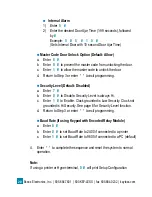
Page 24: ...nter to exit programming Security Level Default Disabled a Enter 7 b Enter 0 to Disable Security Level is always Hi c Enter 1 to Enable Clock grounded is Low Security Clock not grounded is Hi Security...

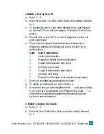
Page 25: ...llowing seven programming options Adding a New User a Enter 1 b Enter the User ID 1 to 500 followed by c Enter the User Code PIN 3 8 digits followed by enter 0 if no code is assigned d Present card or...

Page 26: ...Green LED a Double Slow Flash Slow Flash b Double Slow Flash Fast Flash c Quad Slow Flash Fast Flash d Double Slow Flash Fast Flash e Double Slow Flash Fast Flash f Triple Slow Flash Slow Flash Notes...

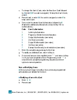
Page 27: ...skip to Step f for no authorizations Code User Authorization 1 Latching Authorization 2 Program or Delete Users Authorization 3 Output AAuthorization see notes 4 2nd Door see notes 5 Output B Authoriz...

Page 28: ...ogram or Delete Users Authorization 3 Output AAuthorization see notes 4 2nd Door see notes 5 Output B Authorization see notes 6 3rd Door see notes 7 Exempt from Security Level restrictions see notes f...

Page 29: ...tes 5 Output B Authorization see notes 6 3rd Door see notes 7 Exempt from Security Level restrictions see notes f Enter to complete programming for this User g To modify an additional User return to S...

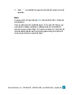
Page 30: ...a User with a Card a Enter 7 b Present card c To delete an additional User return to Step b d If no more Users are to be deleted enter and return to Step 3 or if you have completed all User Programmi...

Page 31: ...yper terminal 0 will print all User ID s Codes and Authorizations Once an authorized user completes steps 1 2 to open the memory any combination of adding modifying or deleting Users can be performed...

Page 32: ...om 28 KPX 34 ERM3 Series Diagrams ERM Circuit Board 2 Terminals 2 3 4 9 10 11 12 to the keypad Terminals 7 8 to Clock or keyswitch contacts if used Terminals 5 6 to Remote Button Release if used Door...

Page 33: ...29 Essex Electronics Inc 805 684 7601 800 KEY LESS fax 805 684 0232 keyless com Typical Hook up Fail Safe or Fail Secure and CCTV Diagram Set Door Open Time to 1 second...

Page 34: ...Essex Electronics Inc 805 684 7601 800 KEY LESS fax 805 684 0232 keyless com 30 Notes...

Page 35: ...31 Essex Electronics Inc 805 684 7601 800 KEY LESS fax 805 684 0232 keyless com Notes...

Page 36: ...that has been discontinued proves defective and if Essex Electronics Inc is unable to repair or replace the product within the terms expressed in this Limited Lifetime Warranty a substitute product m...

Page 37: ...our factory with transportation charges paid by the Buyer Limited Lifetime Warranty The Essex Electronics Inc products with a manufactured date of 5 1 06 to the present date that are covered by this...

Page 38: ...bove under any tort negligence strict liability contract or other legal or equitable theory or for incidental or consequential damages or buyer s cost of effecting insurance coverage The foregoing lim...

Page 39: ...800 KEYLESS 800 539 5377 to obtain an RA All returns must be sent to the factory freight prepaid Collect shipments will not be accepted at any time Standard turnaround time is ten 10 working days fro...

Page 40: ...Essex Electronics Inc 805 684 7601 800 KEY LESS fax 805 684 0232 keyless com...

Reviews: