

1. INTRODUCTION
The SCP-1 Manual Call Point is a component part of a fire alarm system. It is manually operated
to deliver a fire condition alarm signal to a fire control panel.
2. TECHNICAL DATA
2.1.
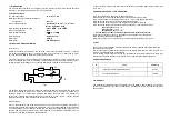
Operating voltage
2.2.
Manual call point’s electrical resistance
in active state
2.3.
Terminal connection
2.4.
Operating temperature range
2.5.
Level of protection
2.6.
Humidity resistance
2.7.
Dimensions
2.8.
Weight
2.9.
Material
- 10 V to 27 V DC
- see Fig.1.
- provided for 0,35 mm
2
– 1 mm
2
cross
section installation wires
- minus 10
°
C - plus 55
°
C
- IP 40
-
(93
±
3)%
at
40
°
C
-
(90
х
90
х
44) mm
-
0,200
к
g
- Red ABS plastics
3. STRUCTURE AND FUNCTIONING
3.1
. Structure
Details of the structure of the SCP-1 can be found on the rear of this leaflet. The SCP-1 consists
of a surface mounting box (pos.1), a carrier unit (pos. 2), a cover (pos. 3), a glass (pos.4), a test
key (pos.6) and a bridge by which the current value is selected.
There are four holes for wall mounting and a cable entrance located on the rear of the base. The
carrier unit consists of a carrier, microswitch, a circuit board and a partition. LED indicator, current
limiting resistors, the M bridge and a connecting terminal are mounted on the circuit board.
Fig.1
The partition, fixed to the carrier unit closes the microswitch and the circuit board. The carrier unit
(pos.2) is connected to the base my means of two screws (pos.5). The glass is placed in the
partition’s groove so it closes the microswitch and retains the circuit open. The manual call
point’s cover is fixed to the carrier unit by means of a screw. A sticker with a relevant graphic
image is placed on the glass, indicating the exact point of breaking.
3.2.
Functioning
When a fire condition arises in the protected area the cover glass is to be pressed strongly. As a
result the glass breaks and releases the microswitch. The circuit closes allowing current to flow at
a value dependant on the resistor’s values and the operating voltage values (typical for the
specific type of the fire control panel). An alarm signal for a fire condition is delivered to the fire
control panel. The LED illuminates to show activation.
To reset the SCP-1 remove the front cover and replace the activation glass. (only use ESP type
G-1 Glass.)
4. PREPARING THE SCP-1 FOR OPERATION
4.1.
Unpack the delivery and check for its completeness.
4.2.
Feed the connection cables through the rear cable hole of the back box.
4.3.
Fix the back box to a flat wall at a height of 1.2 – 1.5 m using appropriate fixings.
4.4.
Remove the cover by unscrewing the supporting elements.
4.5.
Remove the carrier unit (pos.2) and the glass (pos.4) after unscrewing.
4.6.
Connect the cables from the fire alarm panel to the SCP-1s’ terminals as follows:
-
input / output (+ )
and
“+”
;
-
input / output ( - )
and
“ - ” ;
-
shielded wire (S)
and
“S”.
Cut the bridge in order to select the required active state current values.
4.7.
Place the carrier unit (pos.2) in the base and fix it using the two screws (pos.5).
4.8.
Check the glass for signs of damage.
4.9.
Place the cover (pos.3) onto the carrier unit (pos.2) and tighten the screw (pos.5).
5. TEST
5.1.
Test the correct operation SCP-1 by inserting the test key supplied into the test slot at left
hand side of the unit’s base.
5.2.
Turn the test key clockwise until the glass moves slightly forwards and a “click” is heard. The
SCP-1’s red LED should now be illuminated.
5.3.
To restore normal condition turn the key anticlockwise to the initial position and lightly pres
the glass in an upward direction until a further “click” is heard and the LED extinguishes.
6. SERVICE SCHEDULE
N
Task
Periodicity
1
Inspection for visible physical damage
weekly
2
Test correct operation
monthly
330
Ω
M
+
˘
1 k
Ω
D
K
S
7. WARRANTY
The manufacturer guarantees product compliance with the EN54-11:2001 Standard. The warranty
period is 36 months from the date of manufacture, providing the service requirements (5) have
been applied to.