13
6. Installation and commissioning
1. Carefully remove the parts from the packaging. Make sure that you have really removed all
parts before you dispose of the packaging materials in an environmentally friendly manner.
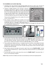
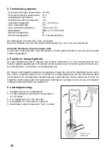
2. Choose a suitable location for the watering computer. It
should be noted that the irrigation computer must always
be attached above the water level of the water storage
tank. The mounting height above the lowest water level is
a maximum of 2 m (see Fig. 4). The control unit must be
mounted vertically (Fig. 1). This avoids the formation of air
in the membrane pump and thus a failure of the system.
There are four elongated holes on the sides of the control
unit for mounting (Fig. 1).
3. Now choose a sunny, shadow-free location for the solar
module within reach of the 3 m long cable. If the 3 m cable
is too short, then a 5 m extension cable (esotec item no .:
101740) is available as an accessory. The solar module can be plugged into the ground using
the supplied ground spike (Fig. 4).
4. Lay the cable of the solar module carefully and without tripping over to the watering computer.
Insert the plug on the cable of the solar module into the “INPUT DC 12V” socket (Fig. 2 / point
4) of the watering computer. Secure the plug connection by unscrewing the protective cap.
When the sun shines on the solar module, the integrated battery is now charged.
5. Then position your water tank max. 2 m below the control unit (Fig. 4). Now attach the black
suction hose firmly to the connection of the filter (Fig. 3 / point 1). Now slide the water level
sensor (Fig. 3 / point 2) into the mount on the filter housing. Please make sure that the sensor
points do not face the hose.
6. Now insert the plug on the water level sensor cable firmly into the “WATER LEVEL” socket
on the watering computer (Fig. 2 / point 2) and secure the plug connection by unscrewing the
protective cap.
7. Push the other end of the suction hose firmly onto the “WATER INLET” connection (Fig. 2 /
point 1) of the watering computer.
Note: Please note that all cables and hoses are laid carefully and without tripping hazards.
1
2.
1
2
4
1
2
Sensor points
3.
4.
max.
2 m


