


Page 32
06-Mar-1997
VME4ST Backplane technical manual
Doc. VLT-MAN-ESO-17130-0992
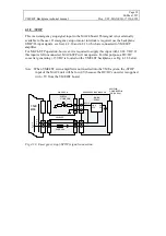
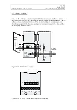
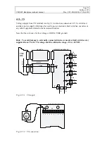
4.3.1 Motor
The stepper motor shall be connected to PH1-PH5 pins as shown in fig 4.3.B. The motor
must under no circumstance be connected to ground.
See also sect. 4.2.1.
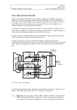
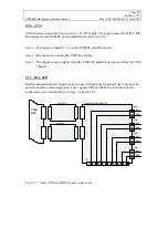
4.3.2 Encoder
The encoder signals are routed from the encoder via function connectors CH1-CH4 to the
MAC4 unit. The use of encoder is optional.
Signal reference for encoder signals are GND pins 10 and 11 in the motor connector.
Note (Important !)
: If no encoder is used, refer to Section 4.1.5 for encoder input
termination !
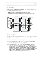
4.3.3 Limit switches (UL and LL)
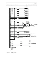
If the use of limit switches is required, they should be connected as shown in Fig. 4.3.B. It is
possible to use any kind of normally closed (N.C.) switch like a micro-switch, transistor
output (open collector) or relay contacts. The limit switch must open on limit condition, and
close to GND (pin 10 or 11 in the motor connector) on normal condition, hereby enabling the
motor.
The limit inputs are distributed to MAC4-STP controller and VME4ST amplifier internally
on VME4ST backplane. Limit signals are
not
latched on either MAC4-STP nor VME4ST
amplifier, and thus the user must make sure that limit signals are active long enough to allow
the motor to stop. If this is not done, and the motor has enough inertia to continue past the
limit switch (which then again would signal off-limit condition), the motor will be enabled
again and could possibly cause damage.
If no limit switches are required, like on a filter wheel, both inputs UL and LL must be
jumpered to GND (pin 10 or 11 in the motor connector).
4.3.4 Reference position switch (HOME)
This signal is, for each axis, routed to the corresponding pin on the MAC4 motion controller.
See sect 4.1.9 and MAC4 manual for further details.
If the use of reference position (index) switch is required, they should be connected as shown
in Fig. 4.3.B. It is possible to use any kind of normally closed (N.C.) switch like a micro-
switch, transistor output (open collector) or relay contacts. The switch must open on
reference position, and close to GND (pin 10 or 11 in the motor connector) on normal
condition.