Model 75K2 service manual, SM75K2_0413 Page 5
eskridge, inc. olathe, KS. 913-782-1238 www.eskridgeinc.com
5)
Inspect the planet gear
(7b)
bearing bore, planet shaft
(7c)
and bearings
(7e & 7f)
. Check for spalling, bruising or other
damage. Replace components as necessary.
6)
Remove roll pins
(7g)
from primary planet shafts
(7c)
using
a 3/16 inch pin punch.
reassembly
1)
Rebuild primary planet carrier assembly in reverse order
using any needed new parts.
2)
Install bearing
(7e & 7f)
into planet gear
(7b)
. Place one
thrust washer
(7D)
on each face of the planet gear. Install
gear assembly into carrier
(7a)
.
3)
Planet shafts
(7c)
should be installed with the chamfered
end of the 3/16 inch hole towards the outside diameter of the
carrier
(7a)
; this will aid in alignment of holes while inserting
roll pins
(7g)
.
4)
Drive roll pin
(7g)
into the carrier hole and into the planet
shaft to retain the parts. Repeat for remaining planet gears.
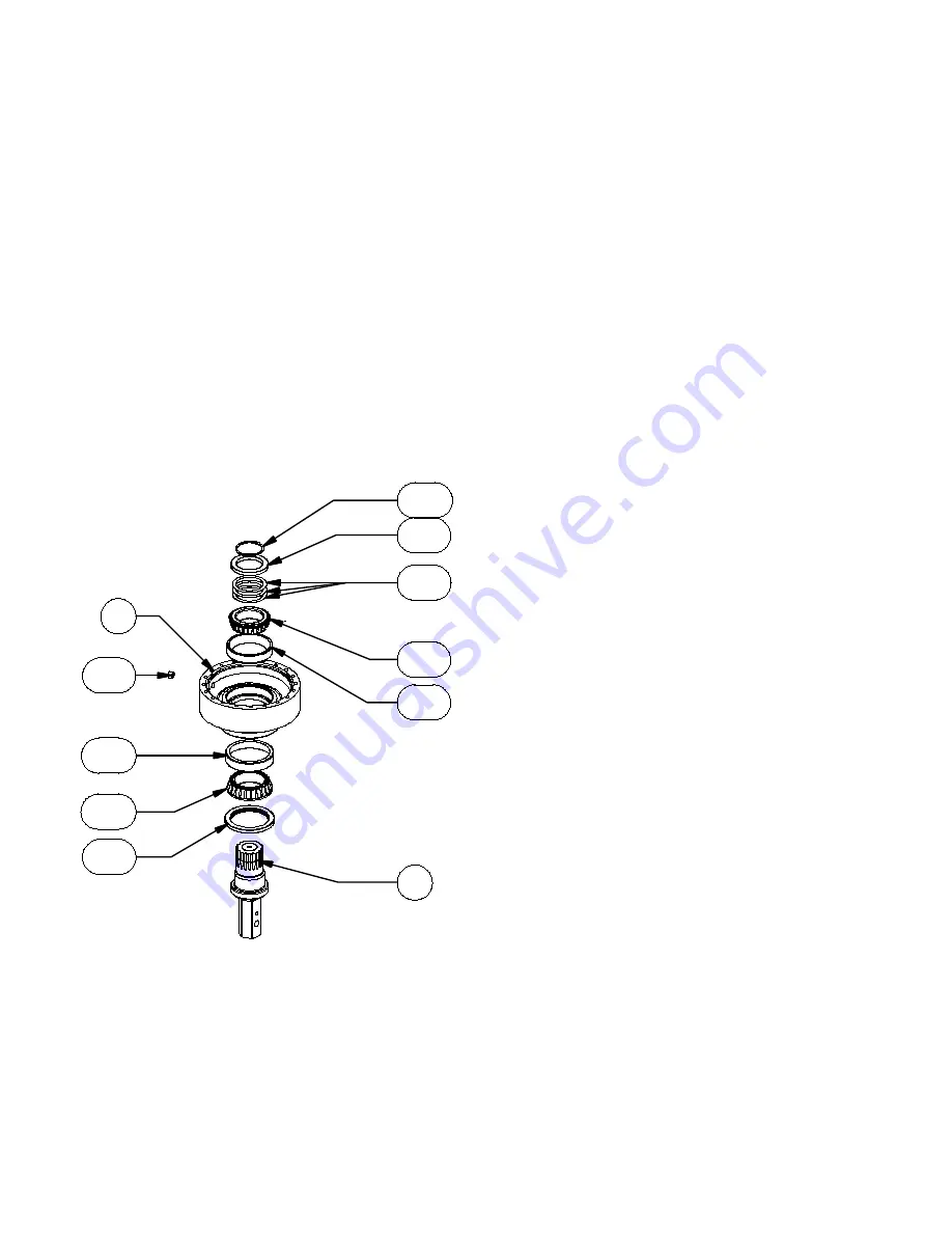
base Subassembly
(items 1, 8, 11a, 12a, 12b, 12c, 12D, 14a, 16a, 16b, 16c)
Disassembly
1) Remove the retaining ring
(16c)
, support ring
(16b)
and
shims
(16a)
.
caution: Since the output shaft is no longer retained, care
should be taken to avoid personal injury. care should also be
taken not to damage it when it is pressed through base.
2)
Base
(1)
should be set shaft side down, as shown, on a plate
or table. Press output shaft
(8)
through the bottom of base
by applying a load to top end (internal end) of shaft until it
passes through inner shaft bearing cone
(12a)
.
note: removing the shaft from the base assembly damages
the shaft seal and the seal will need to be replaced.
3)
A gear puller may be used to remove the outer bearing cone
(12c)
from the shaft
(8)
. If reusing old bearing cone, do not
pull on or damage roller cage. Remove the shaft seal
(11a)
from the shaft for replacement.
4)
Inspect inner and outer bearing cups
(12b & 12D)
. If cups are
damaged, drive them out using a brass drift and utilizing the
bearing knock-out notches in the base
(1)
reassembly
1)
Clean all foreign material from magnetic oil plug
(14a)
locat-
ed on the side of the base
(1)
.
2)
Place base
(1)
(output side up, opposite shown) on the ta-
ble.
3)
Apply a layer of lithium or general purpose bearing grease to
the roller contact surface of outer bearing cup
(12D)
.
4)
Press outer bearing cone
(12c)
(large end down as shown)
onto the shaft
(8)
until it seats against the shoulder.
note: Press bearing cone onto output shaft by pressing on in-
ner race only. Do noT press on roller cage, as it may damage
bearing.
5)
Place the shaft
(8)
with the bearing
(12c)
into the base
(1)
.
6)
Flip this assembly, resting the base
(1)
on the end of the out-
put shaft
(8)
.
7)
Apply a layer of lithium or general purpose bearing grease to the
roller contact surface of the inner bearing cup
(12b)
. Press the
inner bearing cone
(12a)
(large end up as shown) onto the
shaft
(8)
until it is seated against inner bearing cup.
8)
Without the shaft seal
(11a)
installed, the preload may result
in a rolling torque that varies between 50 to 300 in-lb. The
bearing preload should be tailored to your application; a low-
speed application may require a high pre-load, high-speed
applications usually benefit from low pre-load. Adding shims
(16a)
will increase the pre-load on the bearing set. Determine
your pre-load requirement and install shims to obtain this pre-
load. Place the support ring
(16b)
over the shims
(16a)
and
install the retaining ring
(16c)
into the groove in the shaft
(8)
.
9)
Lubricate inner lip of new shaft seal
(11a)
and slide it onto the
shaft
(8)
and over the shaft seal diameter then press the seal
into the base bore
(1)
.
16B
16C
16A
12A
12B
14A
1
12D
12C
11A
8


