ESI U46 SE User Manual Download Page 5

U46 SE 

ESI


2. Description of U46 SE 
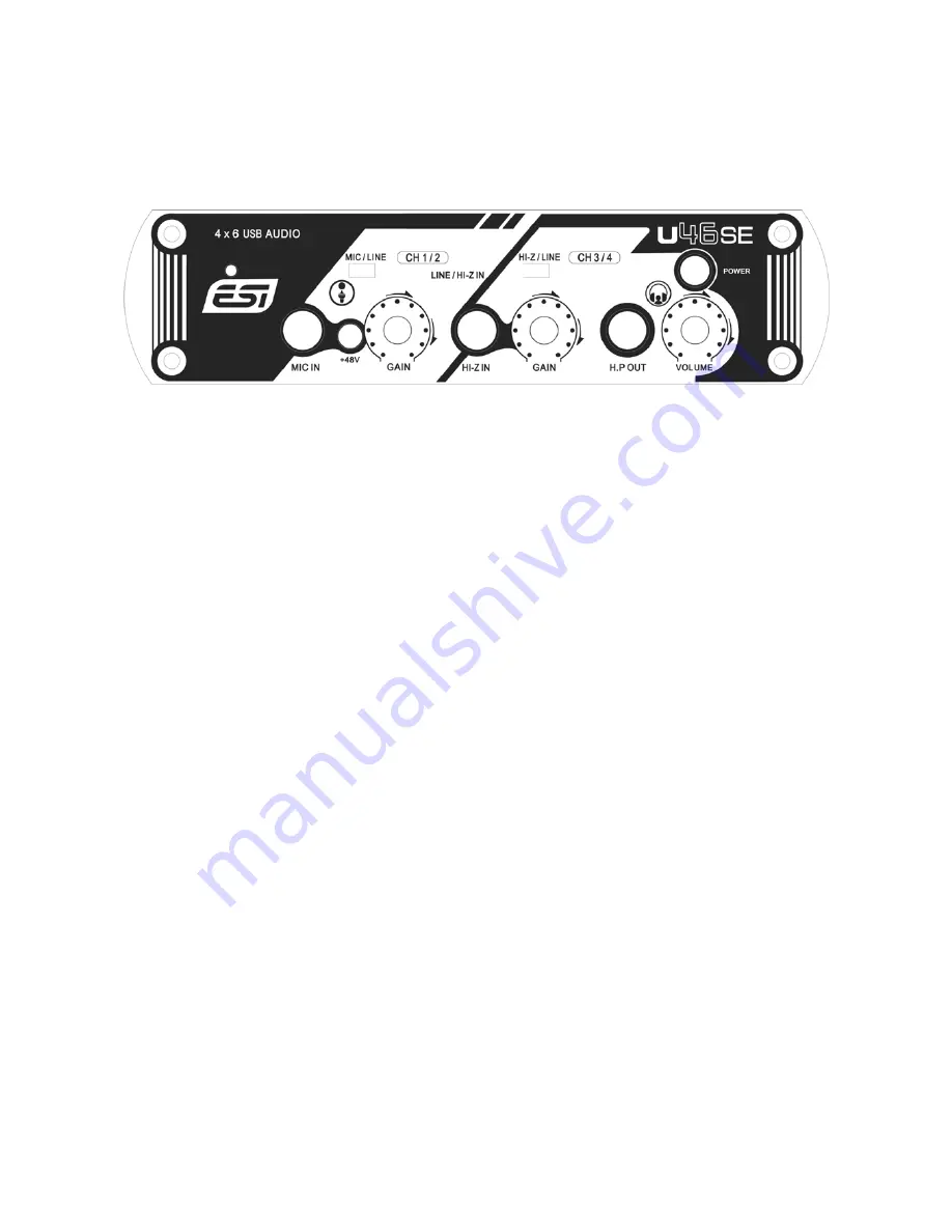
2.1 Front Panel 


(1) Channel 1/2 input connector (CH 1/2) 

Input source (MIC/LINE) selector

: This is where you select input sources of channel 1/2. 

MIC IN connector

: Connect your microphone to this balanced 1/4” connector. 

+48V


phantom power switch

: 48V DC phantom power to input channels 1/2 by 

pressing the button. 

GAIN control for microphone input

: Control input level of microphone. 

(2) Channel 3/4 input connector (CH 3/4) 

Input source (Hi-Z/LINE) selector

: This is where you select input sources of channel 3/4. 

HI-Z IN connector

: Connect an electric guitar or bass guitar to this unbalanced 1/4” connector. 

Only unbalanced 1/4” phone jack connection is possible via this input. 

GAIN control for Hi-Z input

: Control the input level of a connected electric guitar via this 

control knob. 

(3) Headphone output (HP OUT) with Headphone volume control

: Monitor all input sources 

and output sources through the headphone output. The output level can be adjusted with the 
control knob.


(4) Power switch

: Allows you to turn on / off the unit. 


5

Summary of Contents for U46 SE

Page 1: ...4 in 6 out USB Recording Interface User s Guide...

Page 2: ...ESI Copyright 2007 Revision 1 June 2007 www esi audio com...

Page 3: ...stallation 6 3 1 Minimum system requirements 6 3 2 Installation 7 4 Driver Installation 7 5 U46 SE Control Panel 9 5 1 Pull Down Menu 9 5 2 Input section 10 5 3 Output section 11 5 4 DirectWIRE 11 6 A...

Page 4: ...anual and familiarize yourself with the U46 SE s features and operation You may also want to refer to your audio software s documentation to better understand how the U46 SE s features are integrated...

Page 5: ...l 3 4 input connector CH 3 4 Input source Hi Z LINE selector This is where you select input sources of channel 3 4 HI Z IN connector Connect an electric guitar or bass guitar to this unbalanced 1 4 co...

Page 6: ...line level inputs for line level sources like tape decks mixer outputs CD Players etc 4 Output 1 6 You can use these outputs to connect to various external devices or for a 5 1 surround connection 5 M...

Page 7: ...the connection of U46 SE the operating system automatically detects it as a new hardware device Modern operating systems like Windows XP Windows Vista or Mac OS X usually detect the hardware directly...

Page 8: ...t Confirm this with Next You will now be prompted to switch on the hardware Switch on the unit with the power switch Follow the messages instructions on screen until no messages are shown any longer T...

Page 9: ...e task bar Clicking on this icon will launch the U46 SE Control Panel 5 1 Pull Down Menu The U46 SE Control Panel includes a pull down menu section that contains the following main configuration optio...

Page 10: ...alog input 1 2 The input level 3 4 is fixed at 0dB The number on the bottom indicates the relative level in dB 2 Input source display This is where you can check current input source selected by the i...

Page 11: ...n be used for routing audio streams internally within applications using EWDM Audio MIDI Drivers exclusively developed by ESI With the DirectWIRE router an application can record from other applicatio...

Page 12: ...kewalk Audition Vegas etc WDM section represents Multi MME application s I O Ex SONAR when using WDM KS PowerDVD WinDVD etc ASIO section represents ASIO application s I O Ex Cubase Logic Reason Nuendo...

Page 13: ...U46 SE ESI EX2 Recording from WinAmp MME to SONAR WDM EX3 Recording from WinAmp MME to Cubase Logic Nuendo ASIO EX4 Recording from GigaStudio GSIF to SONAR WDM 13...

Page 14: ...2 Latency setting and ASIO applications Via Config Latency in the Control Panel it is possible to change the latency setting also called buffer size for the ASIO driver of U46 SE A smaller latency is...

Page 15: ...alog output and mix output line output level 10dBV unbalanced nominal level 6dBV maximum level output impedance 100 ohms ADC Specifications dynamic range 85dB a weighted typical frequency response 20...

Page 16: ...comply with the limits for a Class A digital device pursuant to Part 15 of the FCC Rules These limits are designed to provide reasonable protection against harmful interference when the equipment is o...

Reviews: