


Quick Start
Page 12 of 28
Hardware Manual Doc.-Nr.: E.1108.21 /Rev. 1.0
ECS-CPCIs/FPGA
At first the
.xml
ESI file must be imported into the Workbench:
(It i
s installed in the Slave Stack’s “
driver\ECS-...\ESI\
” folder.)
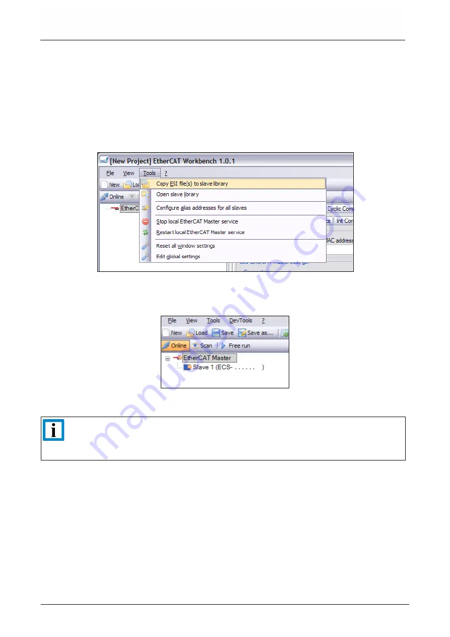
When the Workbench is running, this can be done by the menu entry
Copy ESI file(s) to slave
library
(under menu item
Tools
. Otherwise, the Workbench's start menu entry
Open
slave library
can be used to copy the file manually.
Figure 3:
Installing ESI to EtherCAT Workbench (picture detail)
After the Workbench was (re)started a slave scan can be performed. Use the
Online
button to let
the Workbench connect to its included Master and click the
Scan
button then:
Figure 4:
Scan result
showing “Slave 1 (ECS-CPCIs/FPGA)”, (picture detail)
INFORMATION
These samples show your ECS-CPCIs/FPGA described as
“
Slave 1 (ECS-.....)
”
,
because the actions/behavior described here remain compatible for all esd's EtherCAT
slave devices.
After switching to online mode all slaves are in “Pre-Operational” state. In this state (e.g., indicated
by the orange symbol in
) no process data is exchanged.
Use the
Free run
button to switch your slave to “Operational” mode, see
Then open the
Variables
tab of
Process Data/Image
On this page you see all process variables of the EtherCAT network. For this sample, the first two
entries belong to the ECS-CPCIs/FPGA.
As described earlier, outputs are written, and inputs are read here. So click one of the two
Reread
all
buttons to have the input (“Slave 1 (ECS-CPCIs/FPGA).RxPDO1.Input1”) read.
1.5 Testing the Sample App. with the Workbench


