


Wiring Notes
CPCI-405
Hardware-Manual • Doc.-No.: I.2306.21 / Rev. 3.5
Page 47 of 57
u vw
x wy
u vwz
{
uvw z
|
u vwz
x wy
} ~
~
} ~
~
} ~
~
} ~
~
} ~
~
} ~
~
} ~
~
} ~
~
} ~
~
} ~
~
} ~
~
} ~
~
¡ ¢
£¤ £
¥ ¦§
¨
¦¢
© ª
¡§« ¤§
¨¦¢ ¬
®
®
¯°± ±
² ³
´µ¶
·
¸¹ µ·º»
¼ ½¾¿
À ÁÂÃ Ä
Å
Æ ÇÈÉÊ Ë
ÌÍÎ
Ï ½Ð ÑÁÒ
ÁÓ Ó
½ ÐÑ Ô ¿ÑÅ
ÃÕ
Ó½Ñ ÐÒ ¿
Ó Ö½ ¿Ò× ¿×
×ÃÄ Ø Ò¿
Å
Ù ½ÓÅ¿×
Ú Á½¾
ÛÁØ Ò¿
Ù ½ ÅÖ
¿
Á ¾ÅÖ
Á
Ñ ×
Å¿¾Ô ½ ÑÁŽ ÃÑ
}~ ~
Ü
}Ý Þ
Ý }}·
Þ· »
ßà á
âã
äå ææ ä
å ç
èéê ë ì
åç
êëì í
îæ
ïæ ë
åæ
ð ñ
òòóðô ñõ
ðö÷ó
ßà á
âã
äå ææ ä
å ç
èéêë
ì
åç
êëìí
îæ
ïæë
å æ
ø ùú
ð ö
ûüó
ý
þô ÿ
ð ñ
òòóðô ñõ÷
ðñ
ò òóðôñ õ
ðö÷ ó
Í É
Æ ÇÎ
6.2 Heavy Industrial Environment (Double Twisted Pair Cable)
6.2.1 General Rules
Note:
esd only grants the compliance with directive 2014/30/EC, if the CAN wiring is carried
out with single shielded double twisted pair cables that match the requirements of ISO
11898-2.
The following general rules for CAN wiring with single shielded single twisted pair cable must be
followed:
1
A cable type with a wave impedance of about 120
±10% with an adequate conductor cross
section (
0.22 mm²) has to be used. The voltage drop over the wire has to be considered.
2
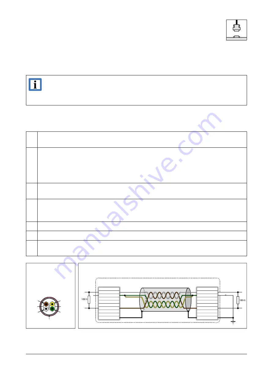
For heavy industrial environment use a four-wire CAN cable.
Connect
two twisted wires to the data signals (CAN_H, CAN_L) and
other two twisted wires to the reference potential (CAN_GND) and
cable shield to functional earth (FE) at least at one point.
3
The reference potential CAN_GND has to be connected to the functional earth (FE) at
exactly one point.
4
A CAN bus line must not branch (exception: short cable stubs) and has to be terminated with
the characteristic impedance of the line (generally 120
±10%) at both ends (between the
signals CAN_L and CAN_H and not to CAN_GND).
5
Keep cable stubs as short as possible (l < 0.3 m).
6
Select a working combination of bit rate and cable length.
7
Keep away CAN cables from disturbing sources. If this cannot be avoided, double shielded
cables are recommended.
Fig. 2: CAN wiring for heavy industrial environment