


Technical Data
Page 18 of 32
Hardware Manual Doc.-Nr.: C.2074.21 /Rev. 1.0
CAN-M.2/402-2-FD
Number of CAN interfaces
2
CAN controller
esdACC in EP4CGX Intel FPGA,
acc. to ISO 11898-1 (CAN 2.0 A/B)
CAN protocol
According to ISO 11898-1
Physical CAN Layer
CAN FD transceiver conforms with ISO 11898-2:2016,
and supports bit rates up to 8 Mbit/s
Electrical isolation
Separation by means of optocouplers and DC/DC-converters
voltage over CAN isolation
(CAN to slot bracket/EARTH;
CAN to Host/System Ground;
CAN to CAN): 1kV DC @ 1s (I < 1 mA)
Bus termination
Terminating resistor can be switched on the optional CAN-
PCIeMini/402-DSUB9 adapter, if required
Connector
Via adapter with DSUB9 connector
Table 6:
Data of the CAN interface
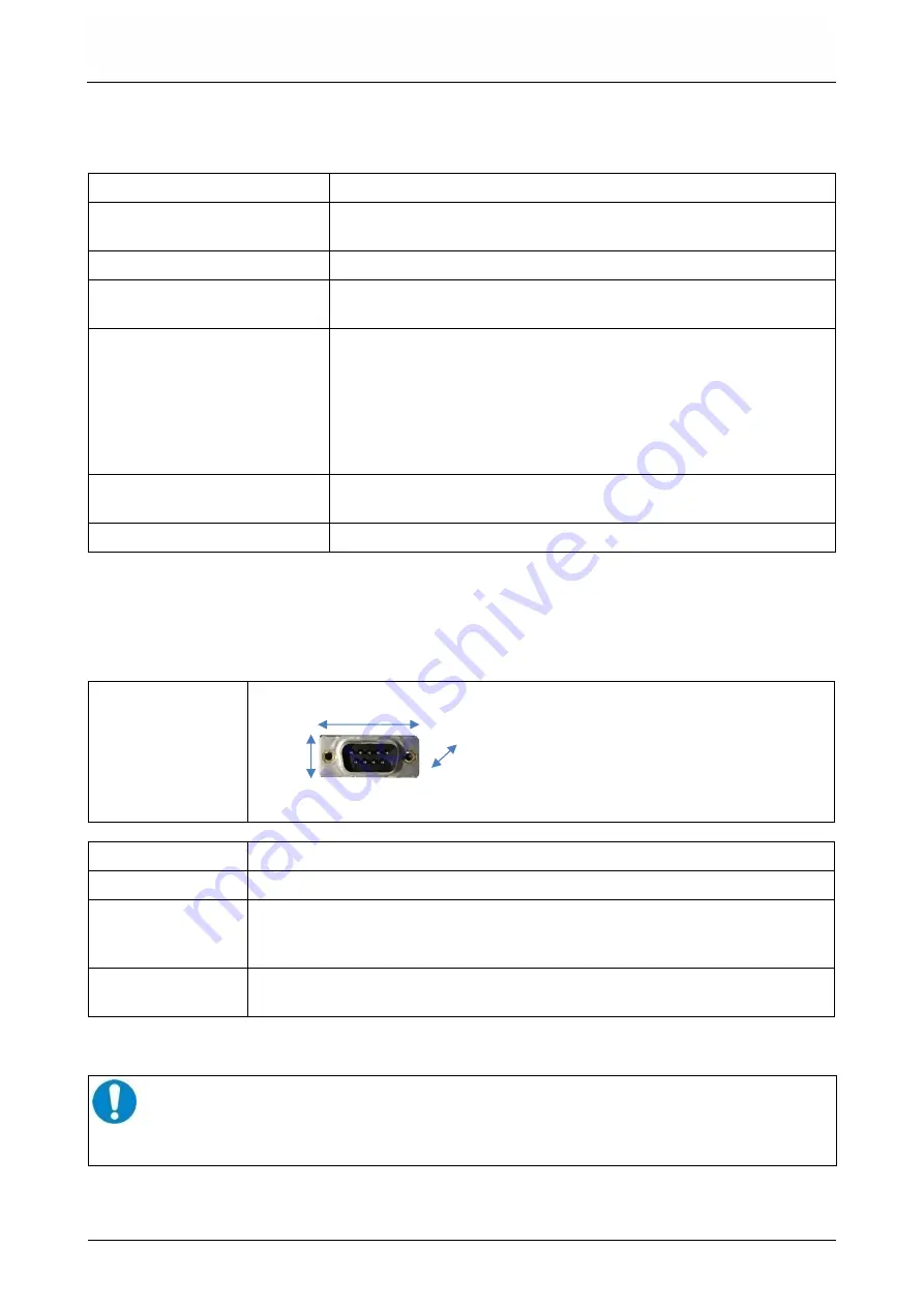
Dimensions
width
width:
hight:
depth:
31.5 mm,
13 mm,
16.5 mm
(10 mm behind front panel)
hight
depth
(adapter only, without cables)
Weight
ca. 8 g
Cable length
150 mm
Connector
Adapter:
Cable:
1x DSUB9 (male),
1x 4-pin Wire-to-Board connector, male (JST, SM04B-SURS-TF)
2x IDE receptacles (JST, 04SUR-32S to JST, 04SUR-32S)
Bolts
2x DSUB bolts
(UNC 4-40 x 5 mm hex nuts with UNC 4-40 x 6 mm thread)
Table 7:
Technical data of the DSUB9 adapter
NOTICE
The adapter is intended to be used with a front panel with 0,8 mm to 1,2 mm thickness!
Don't mount the bolts into the DSUB without a front panel or additional spacers like
washers, because otherwise the bolt threat might damage the DSUB.
6.4 CAN Interfaces
6.5 CAN-PCIeMini/402-DSUB9 Adapter