


i
Overview
CAN-CBM-Clock
Hardware Manual • Doc.-No.: C.2836.21 / Rev. 1.3
Page 9 of 34
!
" "#$ !
"%%&!
'()*+,-
.. /0
12
3 456
789:;< =:> 8
?
@ A8>;= A
B
CDECD
D
" #F&
!$ &!
GHI JK L
M N MOM LP Q
RHS JT
UVW W XYZV [
\ O]V ^X
S_ `G
UVW W XYZV [
U Vab Wc
Hdb Z
Y e
X f
g&!h%
i#$&!jh &
kglm-m
no
pq rr
st
uvw x
k
& h%l
yz &
D
%" {
|
k yD
}
~
245 6
6
5
5
¡
¢
£¤£ ¥¦£
1. Overview
1.1 Description of the Module
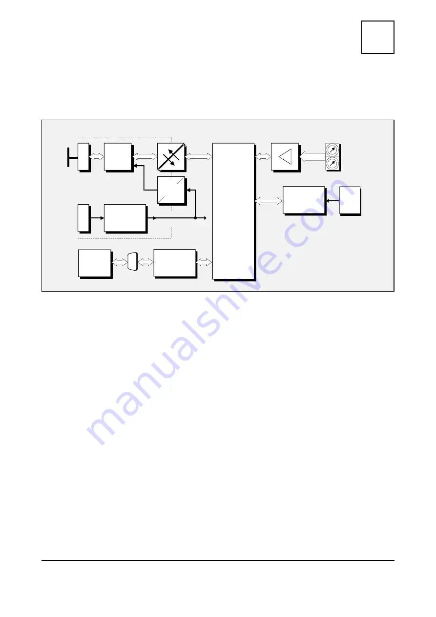
Figure 1: Block circuit diagram of the CAN-Clock module
The CAN-Clock module connects an external DCF77-receiver or an external GPS-receiver (NMEA
protocol 0183-compatible) to the CAN bus. The time information is transmitted as time stamp.
Furthermore the module is equipped with an internal real-time clock (RTC). The time information
of the RTC can be transmitted as time stamp on the CAN bus, if the external clock signals fail to
appear. The time data is given in CANopen format.
The module is operated by an MB90F543 microcontroller, which has built-in SRAM and CAN
controller. The firmware is held in internal flash.
The ISO 11898-compliant CAN interface allows a maximum data transfer rate of 1 Mbit/s. The
CAN-interface is electrically isolated via optocouplers and a DC/DC-converter. The CAN interface
is connected via a 5-pin screw-/ plug connector in Combicon style.
The connection for the external time receiver is designed as serial RS232-interface with a DSUB9
connector.